Signal lamp remote online monitoring method

A signal light and remote technology, applied in the direction of lamp testing, color measurement devices, etc., can solve problems such as interference with equipment operation, reduction of recognition rate, image recognition algorithm lighting environment interference, etc.

Inactive Publication Date: 2013-11-06
黄忠
View PDF4 Cites 12 Cited by
  • Summary
  • Abstract
  • Description
  • Claims
  • Application Information

AI Technical Summary

Problems solved by technology

[0008] These two methods have disadvantages in practical application. The first method needs to lead from the inside of the device. It is an intrusive signal acquisition method, which has the hidden danger of interfering with the operation of the device itself. Common devices such as relays may use this method. One way, but for smart devices, this approach is very unsafe, unless the device itself is designed with a signal light monitoring function, otherwise it is absolutely impossible to use; although the second method is a non-intrusive signal acquisition method, the images in it The recognition algorithm is easily disturbed by the lighting environment, resulting in a decrease in the recognition rate, or even malfunctioning, and with the increase in the number of monitored signal lights, the cost of camera acquisition is too high, so camera technology is only suitable for monitoring a small number of signal lights
[0009] Equipment signal light inspection is a daily work of equipment operation and maintenance and condition maintenance. Due to the technical defects of the above two methods, the automatic monitoring of signal light status has not been widely used, and the online monitoring technology of secondary equipment in substations has not been developed. good development

Method used


Image

  • Signal lamp remote online monitoring method
  • Signal lamp remote online monitoring method
  • Signal lamp remote online monitoring method

Examples


Embodiment Construction

[0027] In order to make the above objects, features and advantages of the present invention more comprehensible, specific implementations of the present invention will be described in detail below in conjunction with the accompanying drawings.

[0028] In the following description, a lot of specific details are set forth in order to fully understand the present invention, but the present invention can also be implemented in other ways different from those described here, and those skilled in the art can do it without departing from the meaning of the present invention. By analogy, the present invention is therefore not limited to the specific examples disclosed below.

[0029] Secondly, the present invention is described in detail in combination with schematic diagrams. When describing the embodiments of the present invention in detail, for the convenience of explanation, the cross-sectional view showing the device structure will not be partially enlarged according to the gener...


PUM


Abstract

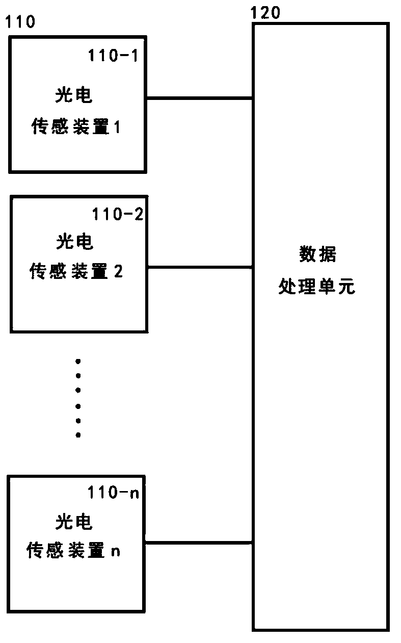
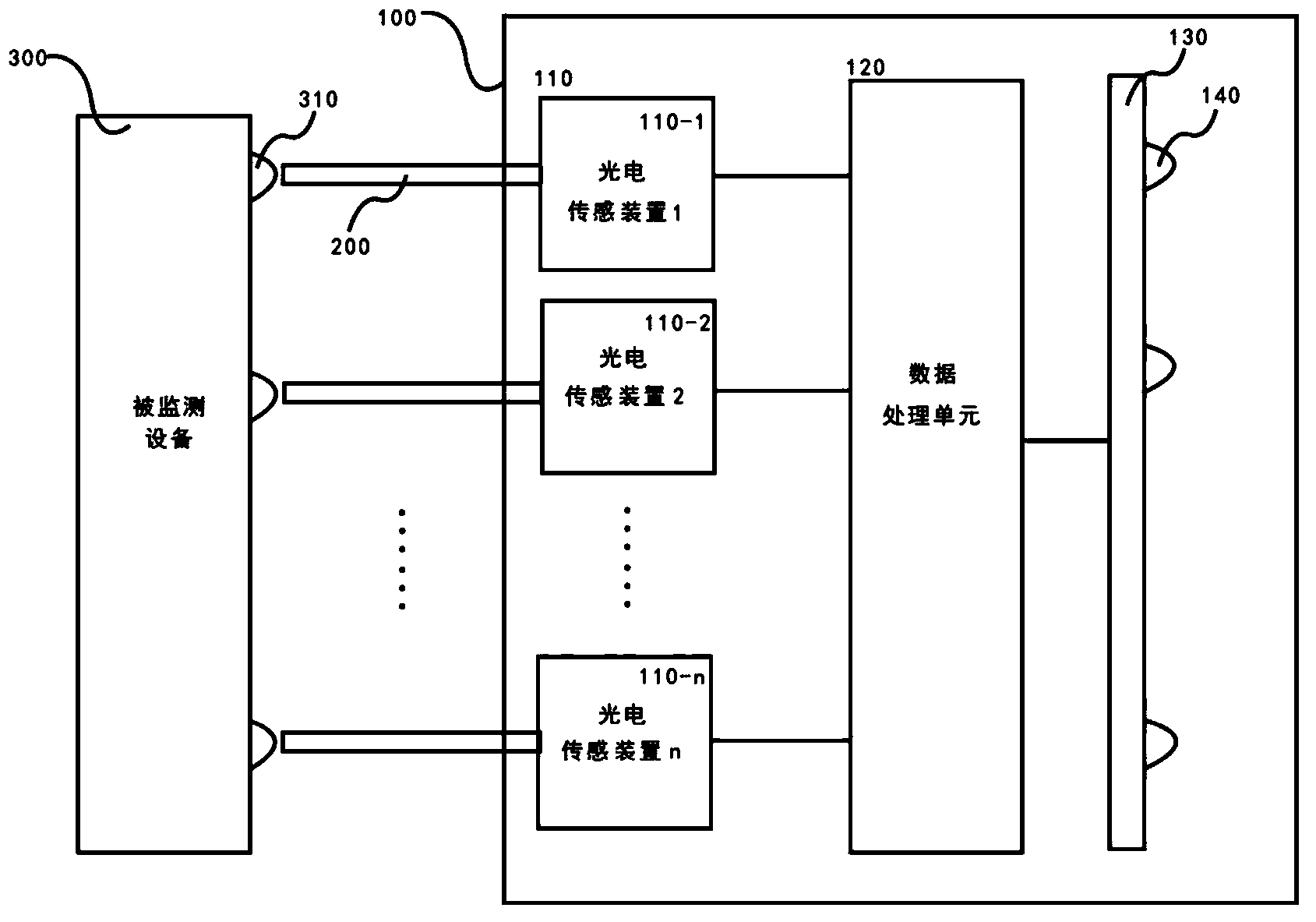
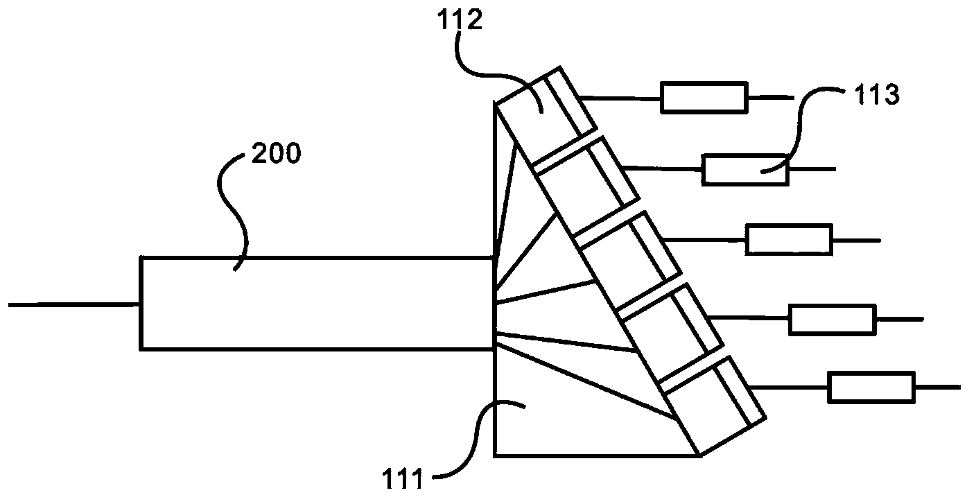
The invention discloses a signal lamp remote online monitoring method. The signal lamp remote online monitoring method comprises the steps that light emitted by a plurality of signal lamps of a monitored device is collected through a plurality of optical fibers, wherein every optical fiber correspond to one signal lamp of the monitored device; the optical fibers transmit the light to a plurality of photoelectric sensors, and every photoelectric sensor is used for receiving and sensing the light transmitted by one optical fiber to obtain electrical signals reflecting the color and the luminance of one signal lamp of the monitored device; a digital processing unit analyzes the electrical signals obtained by the photoelectric sensors to determine the colors and the states of the signal lamps of the monitored device. By means of the signal lamp remote online monitoring method, optical signals can enter a monitoring device through sensors, no electrical connection exists between the monitoring device and the monitored device, and potential risks of interfering the normal operation of the monitored device are avoided.

Description

technical field [0001] The invention relates to a novel method for remote on-line monitoring of signal lamps, which is suitable for on-line monitoring of substation equipment. Background technique [0002] The substation of the power supply company and its affiliated switch station are basically unattended, and there are two main methods for equipment operation and maintenance: [0003] One is condition-based maintenance. In this case, condition-based maintenance needs to increase the frequency of inspections. For routine inspections of substation equipment, the main inspection content is the status of equipment signal lights. Because a power supply bureau has a large jurisdiction and many substations and switch stations, taking Pudong Power Supply Bureau as an example, there are 30 inspectors in Pudong Power Supply Bureau, and there are more than 600 substations and switch stations that need to be inspected, with an average distance of about 10 kilometers , it is difficul...

Claims


Application Information

Patent Timeline
Patent Type & Authority Applications(China)
IPC IPC(8): G01R31/44G01J3/46
Inventor 黄忠谈莹刘新春刘红琴
Owner 黄忠
Why Eureka
Try Eureka