Crawler travelling stacker

A crawler-type and feeding device technology, applied in the field of stacking devices, can solve the problems of lack of flexibility in movement and steering, inability to adapt to dusty materials, and low stacking height, so as to improve operating capabilities, move and turn flexibly, and strong The effect of gradeability

Inactive Publication Date: 2016-07-27
JIANGSU WANBAO MACHINERY
View PDF10 Cites 12 Cited by
  • Summary
  • Abstract
  • Description
  • Claims
  • Application Information

AI Technical Summary

Problems solved by technology

[0003] At present, there are simple stacking devices on the market, which have the following disadvantages: poor stacking efficiency; low stacking height; not suit

Method used


Image

  • Crawler travelling stacker
  • Crawler travelling stacker
  • Crawler travelling stacker

Examples


Embodiment 1

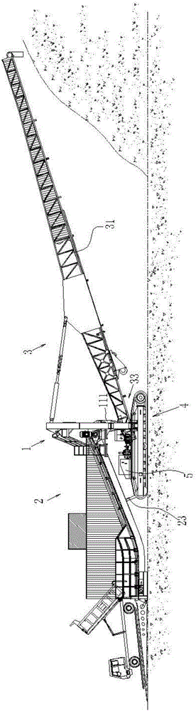
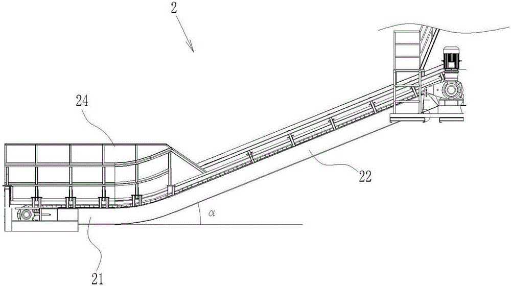
[0036] figure 1 to Figure 6 Schematically shows the first embodiment according to the present invention A crawler-type mobile stacking device , suitable for all kinds of bulk, granular and other loose material storage yards. Including the frame 1 and the feeding device 2, the discharging device 3, and the control system 5 located on the frame 1, the feeding device 2 is connected with the discharging device 3, and the control system 5 controls the operation of the feeding device 2 and the discharging device 3 .

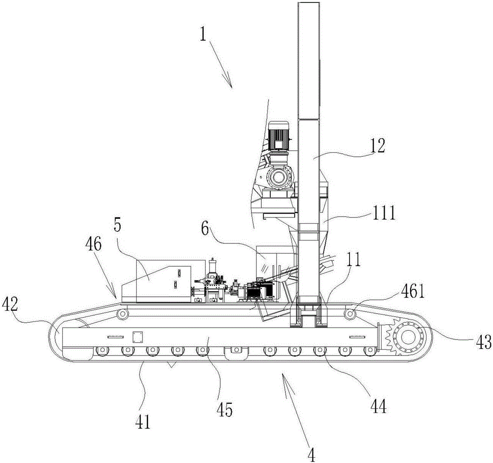
[0037] Such as figure 1 and figure 2 As shown, a traveling mechanism 4 is arranged at the bottom of the frame 1, and the traveling mechanism 4 adopts a crawler traveling mechanism, including a motor, a crawler belt 41, a guide wheel 42, a tow chain wheel 43, several supporting wheels 44, a traveling frame 45 and a tensioning device 46 , Such as figure 2 As shown, the guide wheel 42 and the tow chain wheel 43 are respectively located at the front a...

Embodiment 2

[0050] Example 2 provided A crawler-type mobile stacking device The structure is basically the same as that of Embodiment 1, the difference is that the feeding lifting mechanism and the cantilever pitching mechanism 32 are hoisting mechanisms, and the feeding device 2 and the discharging device 3 are controlled by the hoisting mechanism. The hoisting mechanism includes a stay rope, two Pulley and hoist, the hoist is located on the crawler chassis 11, two pulleys are located on both sides of the upper end of the support 12, and the ends of the stay rope are respectively connected to the middle position of the feeding transmission mechanism 22 and the connecting seat 321 in the middle of the feeding arm frame 311 , the stay rope is wound on the winch on the crawler chassis 11 after the pulley on the upper end of the support 12, and the winch is controlled by the control system 5.

[0051] provided by the invention A crawler-type mobile stacking device , The stacking device mo...


PUM


Abstract

The invention provides a crawler travelling stacker. The crawler travelling stacker comprises a rack as well as a feeding device, a discharging device and a control system which are arranged on the rack. The crawler travelling stacker is characterized in that the feeding device and the discharging device are connected through a slip material transition bin; the slip material transition bin is arranged on the rack; a travelling mechanism is arranged at the bottom of the rack and served as a crawler travelling mechanism; the feeding mechanism comprises a fed material lifting mechanism; the discharging mechanism comprises a cantilever pitching mechanism and a cantilever slewing mechanism; and the control system is used for controlling the travelling mechanism, the fed material lifting mechanism, the cantilever pitching mechanism and the cantilever slewing mechanism. The crawler travelling stacker provided by the invention can directly receive materials from a high-capacity dump truck, so as to improve the operational capability; by adoption of the crawler travelling mechanism, the crawler travelling stacker can move and change directions flexibly and stack the materials at any position of a site, and thus the utilized space of the site is enlarged; and the crawler travelling stacker can adapt to stacking sites with relatively complex working conditions, can pass through a place where bulk materials are stacked, is relatively strong in climbing capability, and can adapt to various working conditions of the stacking sites.

Description

technical field [0001] The invention relates to the field of stockpiling devices, in particular to a crawler-type mobile stockpiling device with high flexibility. Background technique [0002] The stacker is a large-scale construction machine, and its main function is to stack sand, stone, coal and other types of materials so that their stacking height meets the needs of users. [0003] At present, there are simple stacking devices on the market, which have the following disadvantages: poor stacking efficiency; low stacking height; not suitable for dusty materials. [0004] For temporary storage yards, the combination of loaders and excavators is usually used for stacking operations. This method has high operating costs. It uses the loader to transport the materials to be stacked to the corresponding location, and then uses the shovel of the excavator to The bucket picks up the material and puts it at the stacking point. Although the input cost of this method is relatively...

Claims


Application Information

Patent Timeline
IPC IPC(8): B65G65/02B65G69/18
CPCB65G65/02B65G69/181
Inventor 郭永平
Owner JIANGSU WANBAO MACHINERY
Why Eureka
Try Eureka