Signal demodulation method based on machine learning
A signal demodulation and machine learning technology, applied in receiver-specific devices, link quality-based transmission modification, multiple modulation transmitter/receiver arrangements, etc. Problems such as signal demodulation with unknown mode, to achieve the effect of high spectrum utilization and excellent performance
- Summary
- Abstract
- Description
- Claims
- Application Information
AI Technical Summary
Problems solved by technology
Method used
Image
Examples
specific Embodiment approach 1
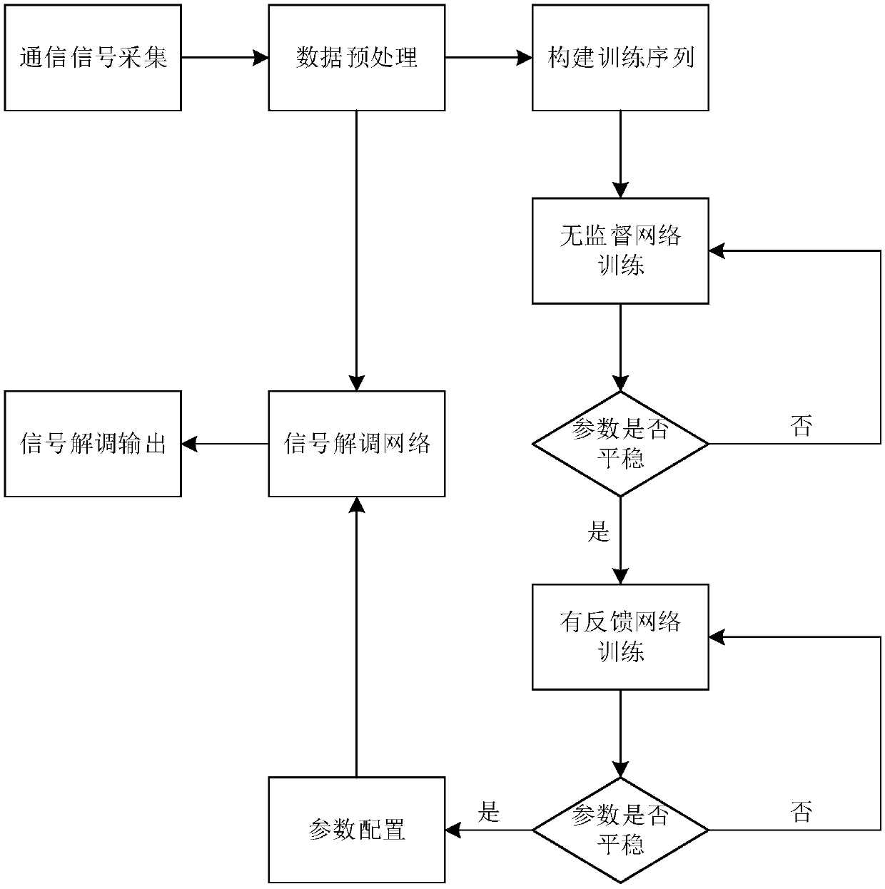
[0029] Specific implementation mode 1: The specific process of a signal demodulation method based on machine learning in this implementation mode is as follows:
[0030] Step 1. Collect the original baseband signal, process the baseband signal to obtain the noise signal, build a denoising self-encoder, perform denoising processing on the noise signal, and obtain the signal after denoising processing; Figure 5 , Figure 6a , Figure 6b shown;
[0031] The denoising self-encoder consists of an encoder and a decoder;
[0032] The specific process is:
[0033] Step 11, constructing the encoder of the denoising self-encoder, and extracting the features of the modulated signal collected;
[0034] Step 1 and 2, constructing a decoder of the denoising self-encoder, denoising and restoring the signal of the extracted feature, and obtaining the signal after denoising processing;
[0035] Step 2, train the neural network in the encoder and decoder in step 1, optimize the parameters...
specific Embodiment approach 2
[0039] Specific embodiment two: the difference between this embodiment and specific embodiment one is that the original baseband signal is collected in the step one, and the baseband signal is processed to obtain the noise signal; the specific process is as follows:
[0040] Step 1. Collect the original baseband signal, carry out carrier modulation on the baseband signal, generate signals of different modulation modes, add Gaussian white noise to the collected carrier modulation signal according to the signal-to-noise ratio range of 0-15dB, with a step size of 1dB;
[0041] Different modulation methods refer to the fact that the original signal is a baseband signal, and then modulated onto the carrier. The modulation method of the signal is uncertain, it can be PAM modulation, or BPSK modulation and other different modulation methods;
[0042]Step 2. Sampling the communication signal after adding Gaussian white noise in step 1, sampling 128 points for each symbol, and 4 communi...
specific Embodiment approach 3
[0047] Specific embodiment three: the difference between this embodiment and specific embodiment one or two is that in the step one by one, the encoder of the denoising self-encoder is constructed, and the specific process is as follows:
[0048] Step 111. Construct the network structure of the encoder of the denoising self-encoder using a convolutional neural network. The network structure includes an input layer, a first convolutional layer, a first pooling layer, a second convolutional layer, and a second pooling layer. layer, output layer;
[0049] The first convolutional layer and the second convolutional layer use the RELU activation function in the form of g(z)=max{0,z}, that is, when the input is less than 0, the output is 0, and when the input is greater than zero, the output is equal to the input;
[0050] The length of the convolution kernel of the first convolution layer is set to 5*5, and the number of convolution kernels is set to 16;
[0051] The length of the ...
PUM
 Abstract
Description
Claims
Application Information
 - R&D
- Intellectual Property
- Life Sciences
- Materials
- Tech Scout
- Unparalleled Data Quality
- Higher Quality Content
- 60% Fewer Hallucinations
Browse by: Latest US Patents, China's latest patents, Technical Efficacy Thesaurus, Application Domain, Technology Topic, Popular Technical Reports.
© 2025 PatSnap. All rights reserved.Legal|Privacy policy|Modern Slavery Act Transparency Statement|Sitemap|About US| Contact US: help@patsnap.com


