RFID demodulator circuit with micro power consumption and high sensitivity

A high-sensitivity, demodulator technology, applied in the field of signal demodulation, can solve problems such as large changes in turn-on voltage, low receiving sensitivity, and increased turn-on voltage, achieving high receiving sensitivity and demodulation sensitivity, and improving anti-noise performance , the effect of reducing complexity

Pending Publication Date: 2016-11-09
GUANGZHOU INTELLIGENT CITY DEV INST
View PDF3 Cites 4 Cited by
  • Summary
  • Abstract
  • Description
  • Claims
  • Application Information

AI Technical Summary

Problems solved by technology

However, when using a diode-connected MOS tube for envelope detection, only when the amplitude of the RF signal is greater than the threshold voltage of the MOS tube can it be demodulated normally, and the receiving sensitivity is low
Although the Schottky diode structure has a small turn-on voltage, its turn-on voltage varies greatly with temperature changes, especially at low temperatures, its turn-on voltage will increase sharply, which affects the demodulation sensitivity, and the Schottky diode and Ordinary RF CMOS process is incompatible, which increases the complexity of the process and affects the cost and application of RFID

Method used


Image

  • RFID demodulator circuit with micro power consumption and high sensitivity
  • RFID demodulator circuit with micro power consumption and high sensitivity
  • RFID demodulator circuit with micro power consumption and high sensitivity

Examples


no. 1 example

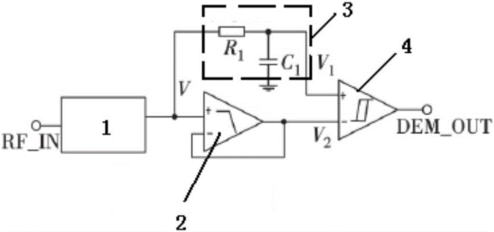
[0044] Aiming at the defects of low receiving sensitivity, low demodulation sensitivity, high power consumption and high process complexity in the prior art, the present invention proposes a brand-new demodulator circuit to realize low power consumption, high Sensitivity and low distortion features. The demodulator circuit structure of the present invention is as figure 1 As shown, the demodulator circuit is mainly composed of an envelope detector, a low-pass filter, a ripple noise filter and a hysteresis comparator. Among them, the envelope detector extracts the envelope of the modulated signal; the ripple noise filter filters out the high-frequency components of the envelope signal, and the output signal is The low-pass filter takes the mean value of the envelope signal as the reference level, and the output signal is V 2 =V×H(S), H(S) is the transfer function of the low-pass filter; the hysteresis comparator will V 1 and V 2 Perform comparison and shaping, and output i...


PUM


Abstract

The invention discloses an RFID demodulator circuit with micro power consumption and high sensitivity, which comprises an envelope detector, a ripple noise filter, a low-pass filter and a hysteresis comparator, and is characterized in that the envelope of a radio frequency signal is extracted through the envelope detector, an input end of the envelope detector is connected with a radio frequency input end, an output end of the envelope detector is respectively connected with an input end of the ripple noise filter and an input end of the low-pass filter, both an output end of the ripple noise filter and an output end of the low-pass filter are connected with an input end of the hysteresis comparator. The RFID demodulator circuit disclosed by the invention comprises the envelope detector, the ripple noise filter, the low-pass filter and the hysteresis comparator, is low in power consumption, and reduces the process complexity and the cost of RFID. The envelope detector is additionally provided with a bootstrap circuit, so that the envelope detector is enabled to still extract an envelope signal correctly when the radio frequency signal is less than a turn-on voltage threshold, and the receiving sensitivity and the demodulation sensitivity are higher. The RFID demodulator circuit can be widely applied to the field of signal demodulation.

Description

technical field [0001] The invention relates to the field of signal demodulation, in particular to an RFID micro-power consumption high-sensitivity demodulator circuit. Background technique [0002] With the rapid development of passive radio frequency identification technology in the fields of transportation, access control security, identification, cargo management, automatic control and anti-theft and anti-counterfeiting, the performance requirements of RFID tags are getting higher and higher, mainly reflected in the communication distance of tags, fast Identification, multi-card identification and cost etc. In RFID tags, the power consumption, sensitivity and environmental adaptability of the demodulator are important factors that affect the communication distance and application fields of RFID tags. At present, the research direction of the demodulator is to improve the demodulation sensitivity and environmental adaptability, and reduce power consumption and cost. The...

Claims


Application Information

Patent Timeline
Patent Type & Authority Applications(China)
IPC IPC(8): G06K19/07G06K19/077
CPCG06K19/0723G06K19/07749
Inventor 胡建国吴劲王德明段志奎李启文周婧
Owner GUANGZHOU INTELLIGENT CITY DEV INST
Why Eureka
Try Eureka