Broadband low minor lobe ridge waveguide gap array antenna

A slot array antenna and ridge waveguide technology, applied in slot antennas, antennas, antenna arrays, etc., can solve the problems of not achieving the ideal feeding effect, increasing the complexity of the feeding network, and deteriorating the performance of the antenna, so as to reduce the impact. , The effect of reducing antenna side lobes and increasing the number of antenna partitions

Inactive Publication Date: 2013-11-06
10TH RES INST OF CETC
View PDF2 Cites 16 Cited by
  • Summary
  • Abstract
  • Description
  • Claims
  • Application Information

AI Technical Summary

Problems solved by technology

However, there are certain constraints in these two methods: increasing the number of partitions in the antenna array can effectively broaden the antenna frequency band, but too many partitions will increase the complexity of the feeding network; adding ridges on the wide side can expand the bandwidth of the antenna at the same time , to control the width of the waveguide and reduce the volume of the antenna, but because of the influence of the ridge, the length of the probe inserted into the ridge waveguide is limited when the ridge waveguide is fed coaxially, and the ideal feeding effect cannot be achieved. In addition, due to the The distance between the radiation slot on the ridge waveguide and the coaxial probe becomes smaller, the radiation field of the two slots next to the probe is greatly affected by the coaxial probe, and when the coaxial feed is applied, the radiation slots on both sides of the probe are mirror-symmetrically distributed. The distance between the two radiation slots in the middle is too small and the coupling is too strong. All of the above factors will cause the performance of the antenna to deteriorate.

Method used


Image

  • Broadband low minor lobe ridge waveguide gap array antenna
  • Broadband low minor lobe ridge waveguide gap array antenna
  • Broadband low minor lobe ridge waveguide gap array antenna

Examples


Embodiment Construction

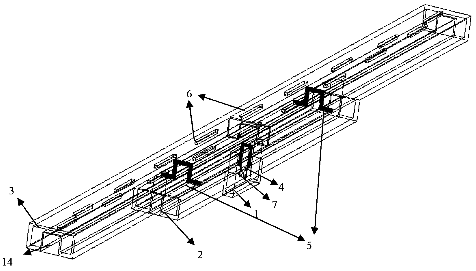
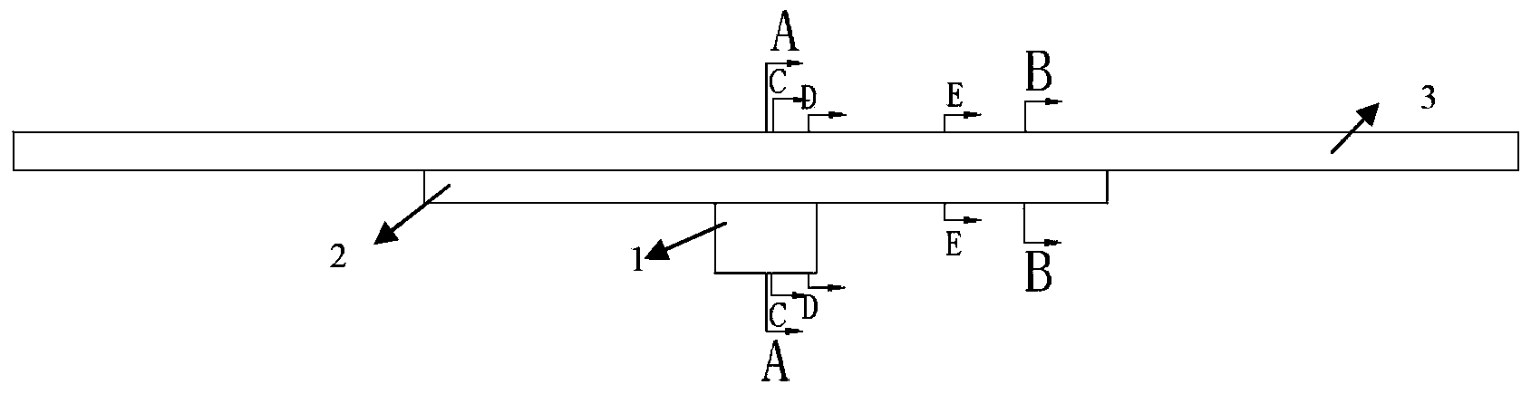
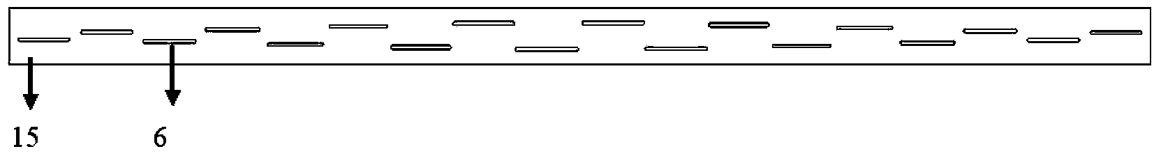
[0023] see Figure 1-11 . The broadband low-sidelobe ridge waveguide slot array antenna described in the following embodiments includes a feeding rectangular waveguide 1 and a feeding slot 4 opened at its end, a concave-convex double-ridged waveguide 2 and its metal opening on the outside of the convex cavity ridge 12 The coupling slot 5 on the outer wall, the radiating single ridge waveguide 3 and the longitudinally offset radiation slot 6 opened by its broad side without ridges, the radiating ridge waveguide metal ridge 14 under the radiating ridge waveguide 3 and the feeding slot 4 are located on both sides of the rectangular It consists of a pair of metal diaphragms 7 in the waveguide 1 . After the radiating single-ridged waveguide 3, the concave-convex double-ridged waveguide 2 and the feeding rectangular waveguide 1 are cut with slits, the three-layer waveguides are welded and pressed from top to bottom to form a ridged waveguide slot array antenna. The radiating singl...


PUM


Abstract

The invention provides a broadband low minor lobe ridge waveguide gap array antenna. A radiation single-ridge waveguide (3) is an antenna array surface coalition formed by connecting two identical ridge waveguides in a butt joint mode, wherein the metal outer wall at the joint divides two waveguide cavities into two subarrays. A feed gap (4) is formed in the end portion of the center of a feed rectangular waveguide (1), wherein the feed rectangular waveguide (1) is nested in a concave ridge of a concave-convex double-ridge waveguide (2), a coupling gap (5) is formed in a convex ridge of the concave-convex double-ridge waveguide, and the convex ridge is embedded in a concave ridge of the radiation single-ridge waveguide. Feed is conducted in two stages, wherein the rectangular waveguide at the bottom conducts feed on the concave-convex double-ridge waveguide in the middle in the first stage, the concave-convex double-ridge waveguide conducts feed on the radiation single-ridge waveguide on the top in the second stage, the rectangular waveguide utilizes the feed gap formed in the rectangular waveguide to complete the feed on the concave-convex double-ridge waveguide, the concave-convex double-ridge waveguide utilizes the coupling gap formed in the concave-convex double-ridge waveguide to complete the feed on the radiation single-ridge waveguide, a radiation gap (6) completes aerial radiation, and the complete ridge waveguide gap array antenna is formed. The broadband low minor lobe ridge waveguide gap array antenna is wide in frequency band, low in minor lobe, and simple and compact in structure.

Description

technical field [0001] The invention relates to a broadband low-sidelobe ridge waveguide slot array antenna mainly applied to the X-band. Background technique [0002] The waveguide slot array antenna has been widely used due to its high utilization efficiency of aperture surface, easy control of aperture distribution, and easy realization of low side lobes. At present, there are two main ways to solve the bandwidth problem of the waveguide slot array antenna: 1) increase the number of divisions of the antenna front; 2) add ridges in the broad side of the rectangular waveguide. However, these two methods have certain limitations: increasing the number of divisions of the antenna front can effectively widen the antenna frequency band, but too many divisions will increase the complexity of the feed network; broadsides and ridges can expand the antenna bandwidth at the same time. , control the broad side size of the waveguide and reduce the volume of the antenna, but due to th...

Claims


Application Information

Patent Timeline
Patent Type & Authority Applications(China)
IPC IPC(8): H01Q21/00H01Q13/10
Inventor 官正涛李佳美
Owner 10TH RES INST OF CETC
Why Eureka
Try Eureka