Circuit breaker for protecting an electrical system

A technology for power systems and circuit breakers, which is applied to emergency protection circuit devices, components of protection switches, circuits, etc., and can solve problems such as heavy manual work, reset of safety devices, and unavoidable damage of circuit breakers

Active Publication Date: 2013-11-06
GEFRAN
View PDF4 Cites 11 Cited by
  • Summary
  • Abstract
  • Description
  • Claims
  • Application Information

AI Technical Summary

Problems solved by technology

[0004] A disadvantage of said known safety device using a fuse is that it needs to be reset after a short circuit in the system, in particular by removing the defective fuse in order to replace it with a new one
Replacing the fuse described is

Method used


Image

  • Circuit breaker for protecting an electrical system
  • Circuit breaker for protecting an electrical system
  • Circuit breaker for protecting an electrical system

Examples


Embodiment Construction

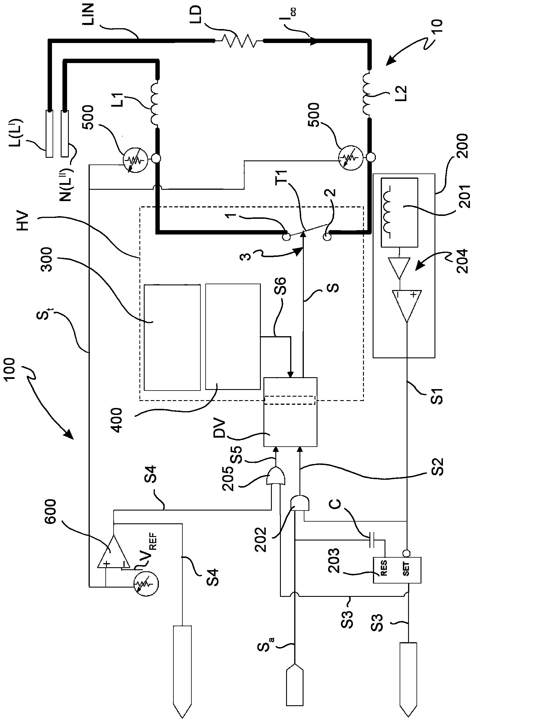
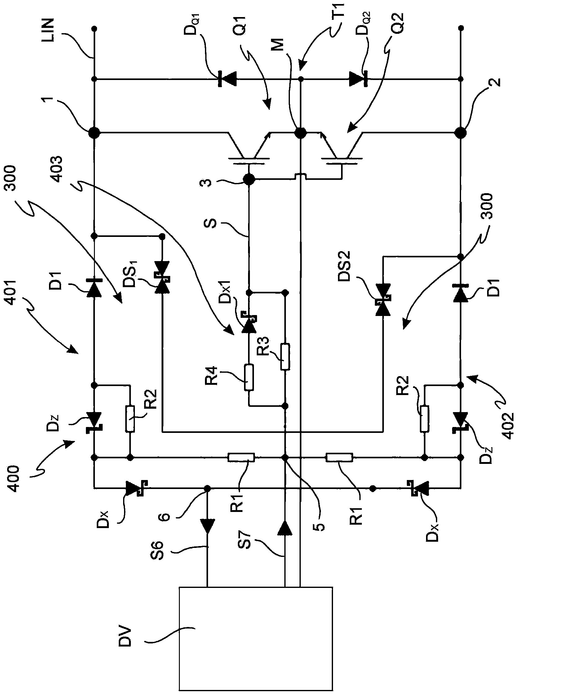
[0014] Refer to the Figure 1-Figure 2 The reference numeral 100 as a whole refers to a circuit breaker for protecting the power system 10 from faults according to the present invention. In said Figure 1-Figure 2 Here, the same reference numerals are used to refer to the same or same elements and components.

[0015] The circuit breaker 100 can be used to connect the main power line LIN with one or more utility devices or “loads” present in the system 10. It should be noted that the system 10 is preferably an industrial system. figure 1 In the example, the industrial system includes a single load LD powered by the main line LIN.

[0016] The load LD represents any industrial electrical load, for example, the heating resistance of a furnace used to process metals, ceramics, and glass or the resistance of an infrared lamp.

[0017] In addition, the circuit breaker 100 of the present invention may be adapted to be connected to a total power line in AC current in a single-phase type or...


PUM


Abstract

The invention relates to a circuit breaker for protecting an electrical system. The circuit breaker comprises a semiconductor switching element with a first and a second electrical terminal connected to a mains supply line and a control terminal. Such switching element is controlled by enabling/disabling a control signal applied to the control terminal for switching between an open/closed status and a closed/open status for connecting/disconnecting at least one load to/from the supply line. Moreover, the circuit breaker comprises a drive adapted to enable/disable the control signal. The circuit breaker is characterized in that it comprises: - a current limiting circuit operatively associated with the mains supply line configured for sending a first signal to the drive for disabling the control signal switching the switching element from the closed status to the open status subsequent to the detection of a current value indicative of a failure in the system; - a voltage regulator circuit connected to the first and to the second electrical terminal, comprising: dissipation means of an electrical energy stored on the mains supply line subsequent to the switching of the switching element from the closed status to the open status, means for limiting a failure voltage between the first and the second terminal generated by peak values of the failure current . Moreover, the circuit breaker comprises an overheating safety circuit of said first and second electrical terminal caused by a non conforming clamping of the electrical wires connected to such terminals.

Description

Technical field [0001] The present invention relates to a device for protecting electric power system circuits for industrial use. In particular, the present invention relates to a circuit breaker for protecting the system from faults that may occur on the mains supply line, on the electrical load, or on the circuit breaker. Background technique [0002] As is known, in modern power systems that are designed for industrial use, safety devices are provided to prevent malfunctions or abnormal phenomena that may disrupt proper system operation. In fact, in the absence of the safety device, any abnormalities and failures may damage utility equipment (power station equipment) or "loads" existing in the system and connect / disconnect the load with the system Both of the circuit breakers. In addition, dangerous situations may occur for the person using the utility device. [0003] Examples of safety devices used in industrial power systems generally include fuses associated with thermal...

Claims


Application Information

Patent Timeline
IPC IPC(8): H02H3/08
CPCH01H83/10H01H71/123H02H3/38H02H7/22H02H3/085H02H5/048H02H7/222H02H3/20
Inventor 乔治·贝林尼乌戈·克劳丹尼
Owner GEFRAN
Why Eureka
Try Eureka