Mandril adjusting device for shaping die set of powder sintering part

A technology for sintering parts and adjusting devices, applied in the field of important parts, can solve the problems of fixed stroke, inability to adjust and damage of mandrels, and achieve the effects of avoiding wear, prolonging service life and reducing binding force.

Active Publication Date: 2013-11-13
严俏敏
View PDF5 Cites 6 Cited by
  • Summary
  • Abstract
  • Description
  • Claims
  • Application Information

AI Technical Summary

Problems solved by technology

[0002] According to the production process of powder compacted products, powder products need to be sintered and shaped to stabilize the shape before they can be used. The stroke of the mandrel used on the existing powder sintered part shaping mold base is fixed and cannot be adjusted. The mandrel is toget

Method used


Image

  • Mandril adjusting device for shaping die set of powder sintering part
  • Mandril adjusting device for shaping die set of powder sintering part
  • Mandril adjusting device for shaping die set of powder sintering part

Examples


Example Embodiment

[0019] The embodiments of the present invention will be further described below with reference to the accompanying drawings.

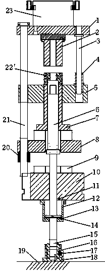
[0020] The upper punch 2 is fixed on the lower surface of the upper punching plate 1 with screws, and the upper punching plate 1 is fixed on the lower surface of the shaping power slider 23 with screws. The punching plate 1 and the female template 5 are connected as a whole.

[0021] There is a through hole in the middle of the mold frame fixing plate 10, a guide groove 101 is arranged in the middle of one side wall, a lower punching plate 9 is fixed around the upper surface, and a cylinder 12 with a lower cavity air pipe 13 and an upper cavity air pipe 11 are fixed in the middle of the lower surface. on the side wall of the rack (not pictured).

[0022] The upper end of the ejection rod 21 is fixed on the upper punching plate 1, and the lower ends of the two diagonally installed ejection rods 21 pass through the female template 5 and the lower punchi...


PUM


Abstract

A mandril adjusting device for the shaping die set of a powder sintering part is characterized in that an upper punching plate, a female die plate, and a lower punching plate are connected into a whole by a guide post and a die stripping rod, and is matched with a die set fixing plate fixed with a cylinder; the die set fixing plate is fixed at the side wall of a rack; the mandril is mounted on a mandril piston and penetrates through the cylinder, the die set fixing plate, the lower punching plate and a lower punch to be connected onto the female die plate; the top end of the mandril is step-cylindrical while the tail end corresponds to and is matched with a check block fixed in a lifting mechanism in an adjusting seat on the rack, or the tail end of the mandril is provided with a telescopic rod to correspond to and be matched with a positioning block on the rack. The adjusting function of the mandril on a shaping machine is increased, the stroke is adjustable, vertical moving for multiple times can be realized, and the original demolding for one time is changed to be demolding for two times, thus greatly reducing the restraining force on the mandril during demolding, avoiding damages such as wearing, tearing and breaking of the mandril and prolonging the service life of the mandril; and the mandril adjusting device for the shaping die set of the powder sintering part can shape products with different inner hole shapes, and the use range of the shaping machine is expanded.

Description

technical field [0001] The invention relates to an important part of a powder sintered part shaping machine, in particular to a powder sintered part shaping mold frame mandrel adjustment device used for shaping powder compacted parts after sintering. Background technique [0002] According to the production process of powder compacts, powder products need to be sintered and shaped to stabilize the shape before they can be used. The stroke of the mandrel used on the existing powder sintered part shaping mold base is fixed and cannot be adjusted. The mandrel is together with the product once. Because the female mold, lower punch, and product are always tightly wrapped outside the mandrel after the product is shaped, the mandrel has to overcome a large binding force to get rid of the lower punch and eject the product, so the mandrel is very Easy to wear, break, damage. Contents of the invention [0003] The technical problem to be solved by the present invention is to provid...

Claims


Application Information

Patent Timeline
IPC IPC(8): B22F3/24
Inventor 严培义
Owner 严俏敏
Why Eureka
Try Eureka