Pin structure made of thermoplastic Z-pin reinforced composite and manufacturing method thereof

A technology for reinforcing composite materials and composite components, which is applied in the field of composite material reinforcement and can solve problems such as the mechanical properties of damaged Z-pins

Active Publication Date: 2017-06-20
NANJING UNIV OF AERONAUTICS & ASTRONAUTICS
View PDF1 Cites 0 Cited by
  • Summary
  • Abstract
  • Description
  • Claims
  • Application Information

AI Technical Summary

Problems solved by technology

The implantation method of Z-pin is mainly ultrasonic vibration implantation, which will damage the mechanical properties of Z-pin to a certain extent, and this implantation method is not suitable for thermoplastic composite materials

Method used


Image

  • Pin structure made of thermoplastic Z-pin reinforced composite and manufacturing method thereof
  • Pin structure made of thermoplastic Z-pin reinforced composite and manufacturing method thereof
  • Pin structure made of thermoplastic Z-pin reinforced composite and manufacturing method thereof

Examples


no. 1 example

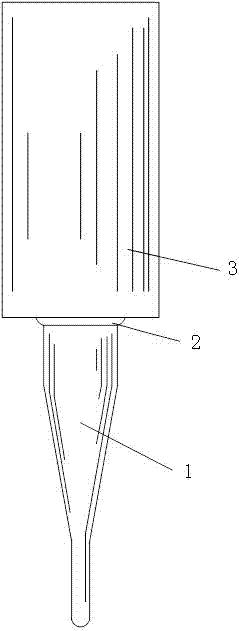
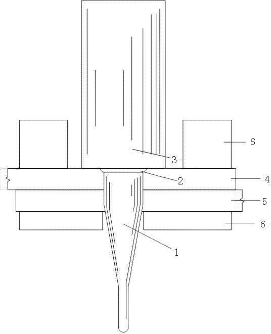
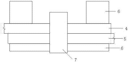
[0032] First example: see image 3 and Figure 4 , a thermoplastic Z-pin reinforced composite pin structure, comprising a thermoplastic composite component 4, a thermoplastic composite component 2 5 and Z-pin7, the thermoplastic composite component 1 4 and thermoplastic composite component 2 5 are connected to each other And the joint is provided with a hole, the hole runs through the first thermoplastic composite material member 4 and the second thermoplastic composite material member 5, and the Z-pin7 is used to be implanted into the hole so as to improve the first thermoplastic composite material member 4 and the second thermoplastic composite material member. 5, the two ends of the Z-pin7 are in the shape of a round cap 8.

[0033] In this embodiment, the direction in which the Z-pin 7 is implanted into the hole is perpendicular to the fiber direction of the first thermoplastic composite material component 4 and the second thermoplastic composite material component 5 .

...

no. 2 example

[0046] Second embodiment: see Figure 5 , a thermoplastic Z-pin reinforced composite pin structure, comprising a thermoplastic composite component 4, a thermoplastic composite component 2 5 and Z-pin7, the thermoplastic composite component 1 4 and thermoplastic composite component 2 5 are connected to each other And the joint is provided with a hole, the hole runs through the first thermoplastic composite material member 4 and the second thermoplastic composite material member 5, and the Z-pin7 is used to be implanted into the hole so as to improve the first thermoplastic composite material member 4 and the second thermoplastic composite material member. 5, the two ends of the hole are in the shape of a countersunk head 9, and the two ends of the Z-pin7 are in the shape of a countersunk head 9.

[0047] In this embodiment, the direction in which the Z-pin 7 is implanted into the hole is perpendicular to the fiber direction of the first thermoplastic composite material componen...


PUM


Abstract

The invention discloses a pin structure made of a thermoplastic Z-pin reinforced composite and a manufacturing method thereof. The pin structure comprises a thermoplastic composite component I, a thermoplastic composite component II and a Z-pin. The thermoplastic composite component I and the thermoplastic composite component II are connected with each other, and a hole is formed in the joint of the thermoplastic composite component I and the thermoplastic composite component II. The hole penetrates through the thermoplastic composite component I and the thermoplastic composite component II. The Z-pin is used for being planted into the hole, so that the connection strength between the thermoplastic composite component I and the thermoplastic composite component Ii is improved. The two ends of the Z-pin are in a pin shape. On the premise of not or slightly damaging fibers in the components to be connected, the thermoplastic composite component I and the thermoplastic composite component II are connected through the method of planting the Z-pin, and the two ends of the Z-pin are processed into the pin shape, so that the connection strength is effectively improved.

Description

technical field [0001] The invention relates to the technical field of composite material reinforcement, in particular to a thermoplastic Z-pin reinforced composite pin structure and a manufacturing method thereof. Background technique [0002] The use of thermoplastics as matrix materials for fiber-reinforced composites has steadily grown, especially in automotive and aerospace applications, mainly because thermoplastics are recyclable and can be processed rapidly. They have better fracture toughness than thermoset resins and can be easily joined using soldering techniques. Thermoplastics, unlike thermosets, can be stored for extended periods of time without any loss of performance. [0003] In the automotive industry, in order to meet low-cost, high-efficiency mass production, the method of breaking parts into parts is adopted, and the production mode of "part production-connection" is proposed. [0004] At present, ultrasonic welding is one of the best welding methods f...

Claims


Application Information

Patent Timeline
IPC IPC(8): B29C65/60
CPCB29C65/601B29C66/02242B29C66/45B29C66/721
Inventor 李勇还大军肖军张向阳李丽莎齐俊伟
Owner NANJING UNIV OF AERONAUTICS & ASTRONAUTICS
Why Eureka
Try Eureka