Pipeline jointing device

A counterpart and pipeline technology, applied in the direction of auxiliary devices, auxiliary welding equipment, welding/cutting auxiliary equipment, etc., can solve the problems of affecting the accuracy of pipeline alignment, cumbersome use, and deformation of the winding structure, so as to be easy to carry and assemble, and improve The effect of improving work efficiency and improving the matching accuracy

Active Publication Date: 2015-07-08
SINOPEC NINGBO ENG +2
View PDF6 Cites 0 Cited by
  • Summary
  • Abstract
  • Description
  • Claims
  • Application Information

AI Technical Summary

Problems solved by technology

Among them, the fixed clip-type external counterpart has a simple structure, but different types of counterparts need to be used for pipes with different outer diameters, which is cumbersome to use; the chain-type external counterpart has a disturbing structure that not only has a certain strength, but also can Free bending in one direction, so that the pipeline is evenly stressed, but the winding structure is prone to deformation during the force application process, and it is difficult to ensure the concentricity and misalignment of the pipeline during the welding process, which affects the alignment accuracy of the pipeline; The alignment accuracy of the inner mouthpiece is generally higher than that of the outer mouthpiece, but the volume of the inner mouthpiece is generally large and the cost is high, which makes it difficult to popularize it in the alignment of the pipeline welding joints in the petrochemical plant
In addition, the matching devices currently on the market use manual assembly, which is not only inefficient, but also the matching accuracy is not high, it is difficult to adjust the slightly wrong edge, and the steps of adjusting the levelness of the flange surface are cumbersome, which is easy to affect the matching accuracy of the pipeline

Method used


Image

  • Pipeline jointing device
  • Pipeline jointing device
  • Pipeline jointing device

Examples


Embodiment 1

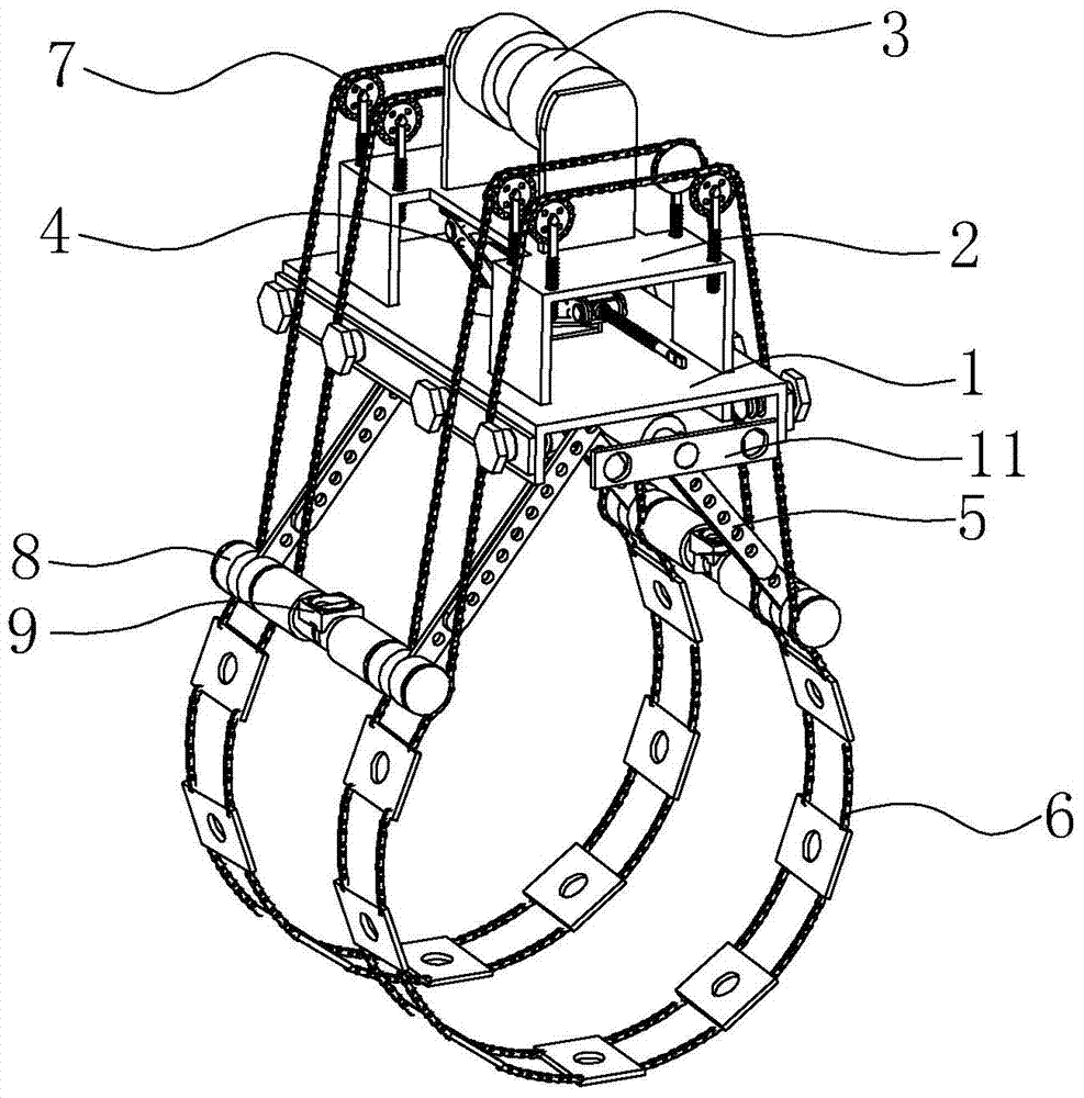
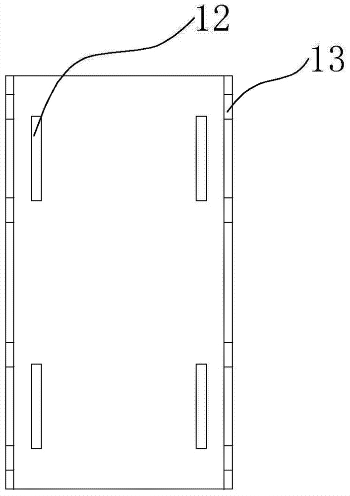
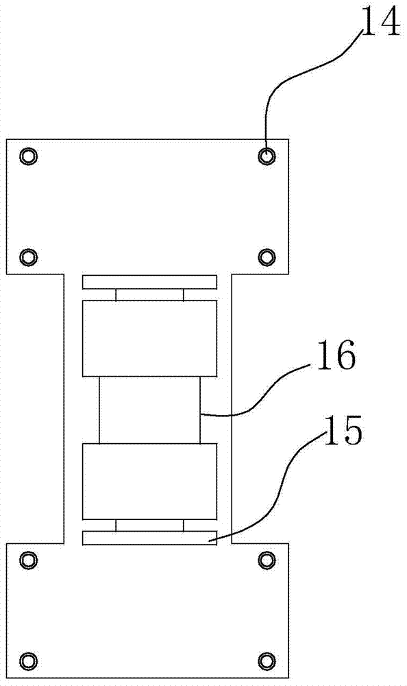
[0025] Embodiment 1: a kind of pipe counterpart, such as figure 1 As shown, it includes a main frame, an upper parallel roller 3, a lifting mechanism 4, a leg 5, a lower parallel roller 8, a chain plate structure 6 and a chain plate adjustment mechanism 7, wherein the main frame includes a main board 1 and a The top plate 2 above the main board 1 and connected to the main board 1, the main board 1 is as figure 2 As shown, the top board 2 is inserted into the main board 1 through the connecting hole 12 between the main board and the top board to realize the connection between the top board 2 and the main board 1; the top board 2 is connected with an upper parallel roller 3, as image 3 As shown, the upper parallel roller 3 includes an upper parallel roller support plate 15 and an upper parallel roller groove 16; the lifting mechanism 4 is located between the top plate 2 and the main board 1, as Figure 4 As shown, the above-mentioned lifting mechanism 4 includes a pivot 17 an...

Embodiment 2

[0026] Embodiment 2: as Figure 1-10 As shown, the present invention adjusts the supporting leg 5 to a suitable angle during the use of the external mouthpiece, and sets the chain plate structure 6 on the pipeline to be matched; the chain 30 is placed on the second guide on the lower side of the supporting leg 5 In the chain groove 53 and the first chain guide groove 20 of the chain plate adjustment mechanism 7, the weld seam distance adjustment pin 35 is inserted into the butt welding seam; the nut 32 is turned to make the chain plate adjustment mechanism 7 move up and down, changing the direction of the chain 30 To the proper position, turn the operating lever 18 so that the pivot 17 rotates accordingly and drives the top plate 2 and the chain plate adjustment mechanism 7 to move up and down, tighten the chain plate structure 6, and complete the preliminary alignment of the pipeline; after completing the above operations, check the weld seam For the reserved amount, adjust t...

Embodiment 3

[0027] Embodiment 3: as Figure 1-10 Shown, the present invention can be combined the various forms of welding mouth group that the external mouthpiece can't finish in the process of using as the inner mouthpiece. Adjust the length and angle of the legs 5, put the counterpart into the pipe; turn the operating lever 18 to make the pivot 17 rotate accordingly and drive the top plate 2 and the upper parallel roller 3 to move, so that the upper parallel roller 3 and the lower parallel roller The shaft 8 fits closely with the inner wall of the pipe to realize fast alignment.

[0028] Due to the relatively high requirements for the levelness of the flange surface, the levelness of the flange surface is related to the effect of the flange connection. In order to make the combination effect better, the present invention provides a flange surface inspection and adjustment structure 11 . When checking and adjusting the flange surface, extract the telescopic joint 42 and the detection a...


PUM


Abstract

The invention discloses a pipeline jointing device comprising a main frame, an upper rolling shaft, a lifting mechanism, support legs, lower parallel rolling shafts, a chain plate structure and a chain plate adjusting structure; the upper parallel rolling shaft is arranged above and connected with the main frame; the support legs are positioned below the main frame and the upper ends of the legs are connected with the main frame; the lower ends of the support legs are connected with the lower parallel rolling shafts; the chain plate adjusting mechanism is arranged above and connected with the main frame; and the chain plate structure is connected with the chain plate adjusting mechanism and the lower parallel rolling shafts. As the chain plate structure is arranged on the jointing device by the connection with the chain plate adjusting mechanism and the lower parallel rolling shaft, the chain plate structure can be easily separated from the main frame to facilitate carrying and assembling, and the application of the construction site; chain plates with adjusting holes are arranged in the chain plate structure, so the precision of pipeline jointing is ensured; and the pipeline jointing device can be used as both an inner jointing device and an outer jointing device and has a wide application range.

Description

technical field [0001] The invention relates to the field of pipeline assembly and welding assurance, in particular to a pipeline matching device. Background technique [0002] The counterpart construction process of pipeline welding is often realized through pipeline counterparts. At present, commonly used counterparts include fixed card type external counterparts, chain type external counterparts and internal counterparts. Among them, the fixed card-type external counterpart has a simple structure, but different types of counterparts need to be used for pipes with different outer diameters, which is cumbersome to use; the chain-type external counterpart has a disturbing structure that not only has a certain strength, but also can Free bending in one direction, so that the pipeline is evenly stressed, but the winding structure is prone to deformation during the force application process, and it is difficult to ensure the concentricity and misalignment of the pipeline durin...

Claims


Application Information

Patent Timeline
Patent Type & Authority Patents(China)
IPC IPC(8): B23K37/053
Inventor 贺贵仁董茂栋杨开宇
Owner SINOPEC NINGBO ENG
Why Eureka
Try Eureka