
Ultrasonic wave transit time measuring circuit by secondary reflection waves

A secondary reflected wave and time-of-flight technology, which is applied to the measurement of ultrasonic/sonic/infrasonic waves, measurement of reverberation time, measurement devices, etc., can solve the problems of high judgment error rate and complex algorithm, and achieve good accuracy.

Inactive Publication Date: 2013-11-13
ZHEJIANG SCI-TECH UNIV
View PDF4 Cites 7 Cited by
  • Summary
  • Abstract
  • Description
  • Claims
  • Application Information

AI Technical Summary

Problems solved by technology

[0006] The purpose of the present invention is to solve the problems in the prior art that the error rate of ultrasonic zero-crossing judgment is relatively large and the algorithm is complex, and the transit time is judged by using the waveform height similarity between the primary received wave and the secondary reflected wave that has a causal relationship

Method used


Image

  • Ultrasonic wave transit time measuring circuit by secondary reflection waves
  • Ultrasonic wave transit time measuring circuit by secondary reflection waves
  • Ultrasonic wave transit time measuring circuit by secondary reflection waves

Examples


Embodiment Construction

[0019] The present invention will be further described below in conjunction with accompanying drawing.

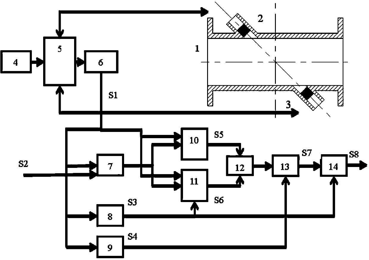
[0020] The present invention utilizes the waveforms of the primary received wave and the secondary reflected wave with a causal relationship, takes the highest point of the amplitude as the reference point for judging the two, opens up the judging window, and uses the position of the upward crossing zero of the waveform as the comparison position , to calculate the transit time. In order to realize the above logical relationship, the circuit system is set up: the first peak detector 10 measures the highest amplitude of the entire waveform sequence; the second peak detector 11 resets the output when each waveform crosses zero, thereby obtaining a single waveform the highest amplitude. When the peak value exceeds the highest point, the two are compared and output as a window signal, and the next first upward crossing zero signal is detected to control the start and stop of t...


PUM


Abstract

The invention relates to an ultrasonic wave transit time measuring circuit by secondary reflection waves. The ultrasonic wave transit time measuring circuit is used on an ultrasonic flowmeter and used for measuring the ultrasonic wave transit time between two sensors through the waveform similarity between primary received ultrasonic waves and secondary reflected ultrasonic waves. The ultrasonic wave transit time measuring circuit comprises a multi-path gating device (5), a programmable amplifier (6), waveform characteristic judging electrical systems (7-13), wherein the multi-path gating device (5) is used for ensuring that excitation signals, the primary received signals and the secondary reflected waves can accurately enter a subsequent circuit; the programmable amplifier (6) is used for processing different magnification time requirements of the primary received signals and the secondary reflected signals; the waveform characteristic judging electrical systems (7-13) are used for controlling the starting up / shutting down of a time counter (14) according to judgment results so as to complete the measurement of the transit time. According to the ultrasonic wave transit time measuring circuit, the energy source of the primary received ultrasonic waves is the same as that of the secondary reflected ultrasonic waves, so that a super-high similarity relation exists between the primary received ultrasonic waves and the secondary reflected ultrasonic waves. Thus, the problem that corresponding waveform characteristics are misjudged is avoided.

Description

technical field [0001] The invention relates to a circuit for measuring ultrasonic transit time by using secondary reflected waves, which is mainly used in time-difference ultrasonic flowmeters to measure the transit time of sound waves between two opposing ultrasonic sensors. Background technique [0002] The transit-time ultrasonic flowmeter relies on detecting the modulation effect of the flowing medium on the ultrasonic signal, and obtains the transit time of the sound wave on the fixed-length channel, thereby deriving the flow velocity data of the medium. At present, ultrasonic flowmeters usually judge the transit time by identifying specific mark points on the waveform, so the judgment of specific mark points on the waveform has become the key technology of time difference ultrasonic flowmeters. [0003] In the prior art, when sending out ultrasonic signals, the main methods adopted include: [0004] 1. Use square wave sequence excitation and set the threshold value. ...

Claims


Application Information

Patent Timeline
IPC IPC(8): G01H7/00G01F1/66
Inventor 鲍敏吴春华沈卫平
Owner ZHEJIANG SCI-TECH UNIV
Learn More