

Optical lens with function of blocking infrared rays and its optical lens
A technology of optical lenses and optical lenses, which is applied in the field of optical lenses, can solve problems such as unfavorable optical lenses and adding optical lenses, and achieve the effect of avoiding image quality
- Summary
- Abstract
- Description
- Claims
- Application Information
AI Technical Summary
Problems solved by technology
Method used
Image

Examples
no. 1 example >
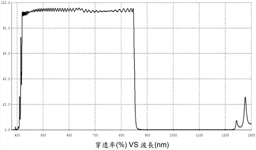
[0087] First please refer to Figure 9 to Figure 14 , which shows the spectrogram according to the first embodiment of the present invention, the optical lens of the present embodiment or the selected optical lens of the optical lens is to form 6 layers of optical film layers thereon, the total thickness of these 6 layers of optical film layers between 500 and 600 nanometers. The optical lenses used here are all made of E48R plastic material produced by ZEONEX Company, and a total of 6 layers of different lenses are stacked on at least one surface (that is, at least one of the object side and the image side) by vacuum evaporation technology. The first material optical film layer and the second material optical film layer of the refractive index are prepared, and Ti is selected here 3 o 5 materials to make the first material optical film layer, and SiO 2 The material makes the second material optical film layer. Please refer to the following two tables for the thickness and t...
no. 2 example >
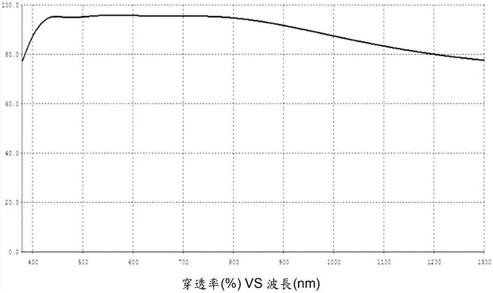
[0103] Please also refer to Figure 15 to Figure 20 , which shows the spectrogram according to the second embodiment of the present invention, the optical lens of the present embodiment or the selected optical lens of the optical lens is to form 8 layers of optical film layers thereon, the total thickness of these 8 layers of optical film layers Between 601 and 900 nanometers. The optical lenses used here are all made of E48R material (refractive index 1.533) produced by ZEONEX, and a total of 8 layers are stacked on at least one surface (ie at least one of the object side and the image side) by vacuum evaporation. The first material optical film layer of the layer and the second material optical film layer are prepared. In order to provide a comparative result in order to integrate various embodiments in this description, here is to select the same Ti 3 o 5 with SiO 2 The material makes the first material optical film layer and the second material optical film layer to ma...
no. 3 example >
[0117] Please also refer to Figure 21 to Figure 26, which shows the spectrogram according to the third embodiment of the present invention, the optical lens of the present embodiment or the selected optical lens of the optical lens is to form 12 optical film layers thereon, the total thickness of the 12 optical film layers between 1201 and 1550 nanometers. More specifically, the optical lenses used here are all based on the main body of E48R material (refractive index 1.533) produced by ZEONEX, and vacuum evaporated on at least one surface (ie at least one of the object side and the image side). A total of 12 layers of high refractive index optical coatings (Ti 3 o 5 ) and low refractive index optical film (SiO 2 ) prepared in a manner. When the optical lens selected in this embodiment is coated with an optical film layer on its object side, please refer to the following two tables for the thickness and total thickness of the first material optical film layer and the seco...
PUM
| Property | Measurement | Unit |
|---|---|---|
| thickness | aaaaa | aaaaa |
| thickness | aaaaa | aaaaa |
| wavelength | aaaaa | aaaaa |
Abstract
Description
Claims
Application Information