
Optical system and method for improving its optical property

An optical system and optical technology, applied in optics, nonlinear optics, coupling of optical waveguides, etc., can solve problems such as inability to effectively adjust chromaticity, poor chromaticity uniformity of optical system 1, and increased production costs.

Inactive Publication Date: 2006-08-23
AU OPTRONICS CORP
View PDF0 Cites 0 Cited by
  • Summary
  • Abstract
  • Description
  • Claims
  • Application Information

AI Technical Summary

Problems solved by technology

[0004] During the manufacturing process, each light-emitting diode will have slightly different color deviations due to individual differences, such as a little reddish or a little bluish, which will cause uneven brightness or color of the applied display panel after emitting light.
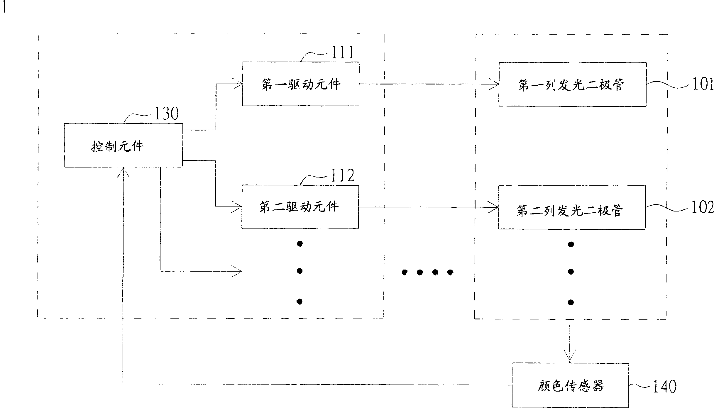
while applications such as figure 1 The traditional method for adjusting chromaticity shown can only adjust the light-emitting diode area close to the color sensor 140 to approach the standard chromaticity (i.e. white light) after light mixing, and for the light-emitting diode area that is too far away from the color sensor 140, Still cannot be effectively adjusted for chroma
Therefore, for the entire display panel, there are still some areas with color shift (for example, some parts are reddish, and some parts are bluish), so the overall chromaticity uniformity of the optical system 1 is still not good; similarly, it cannot be used. like figure 1 The adjustment method shown to achieve the overall brightness uniformity of the optical system 1
If you want to place multiple color sensors on the display panel to solve the problem of uneven chromaticity or brightness, it will greatly increase the production cost and is not applicable

Method used


Image

  • Optical system and method for improving its optical property
  • Optical system and method for improving its optical property
  • Optical system and method for improving its optical property

Examples


Embodiment Construction

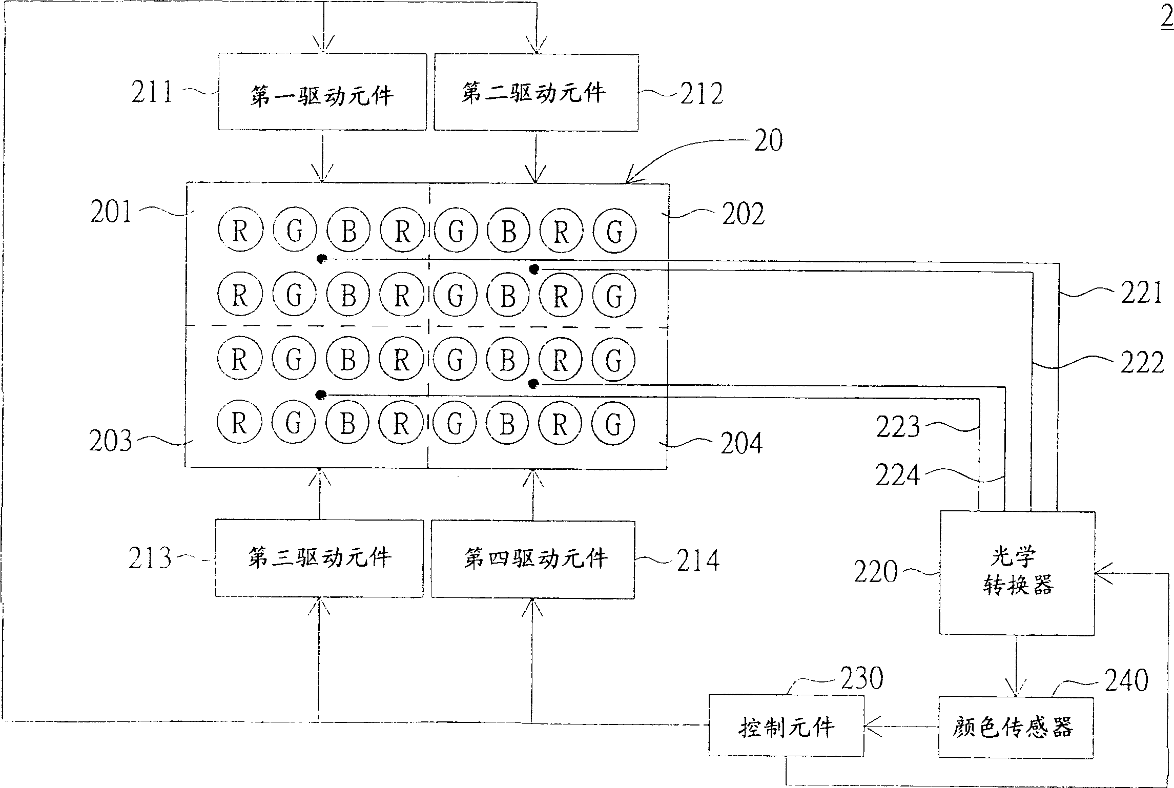
[0037] The present invention proposes an optical system and a method for improving its optical properties. Multiple optical fiber transmission lines and an optical switch are used to correct and compensate the colors in the optical system in different areas, so that the optical properties of the optical system are as follows: Luminance and chroma homogenization. The following uses an embodiment to describe the present invention in detail. However, the embodiment does not limit the scope of protection of the present invention. In addition, unnecessary components are omitted in the diagrams to clearly show the technical characteristics of the present invention.

[0038] Please refer to figure 2 , which represents a schematic diagram of an optical system according to an embodiment of the present invention. In this embodiment, all light sources in the optical system, such as red (R), green (G) and blue (B) LEDs, are divided into four calibration areas, but the invention is not ...


PUM


Abstract

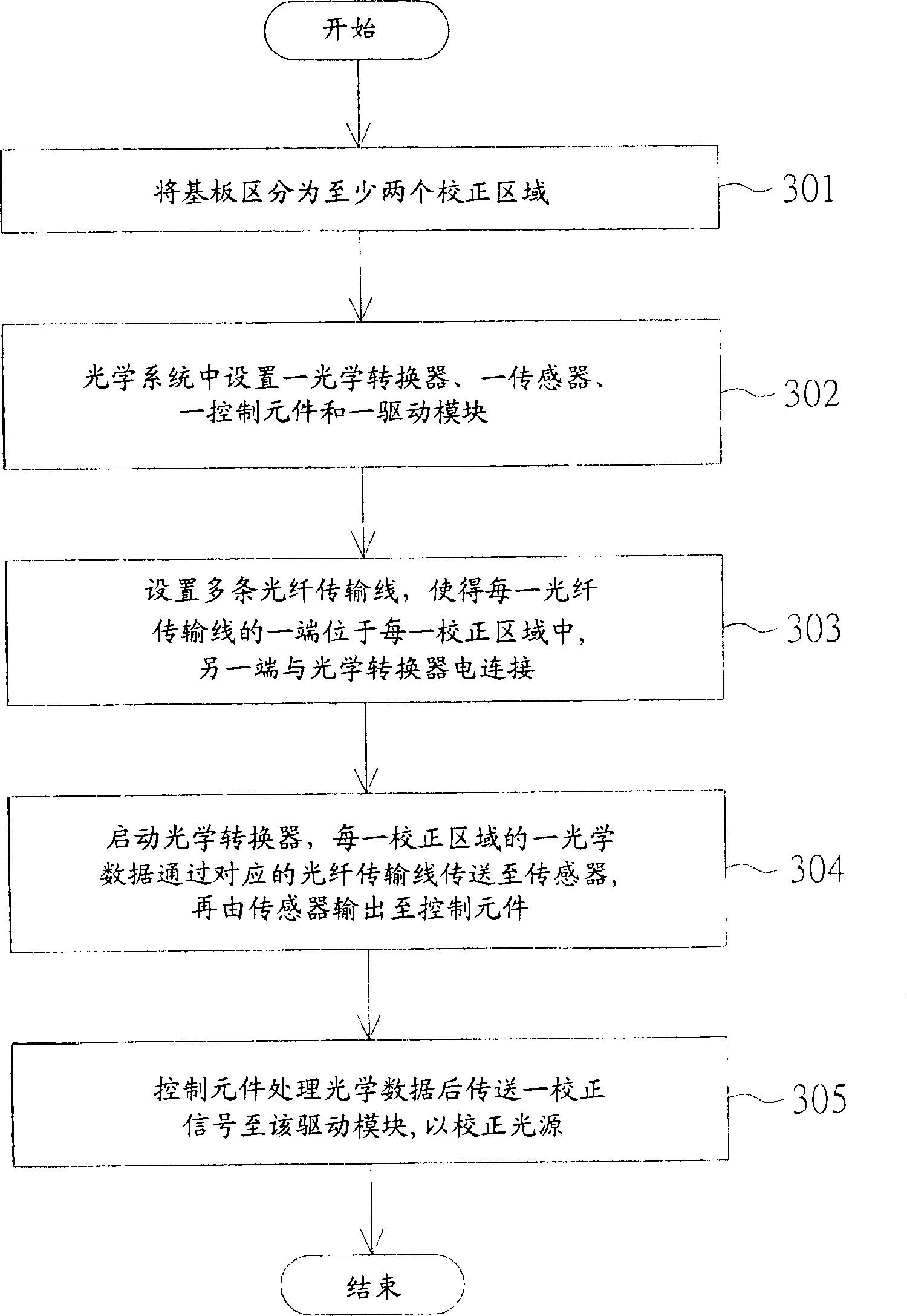
This invention relates to an optical system including a base plate having at least two correction regions, multiple light sources on the base plate, an optical converter, at least two fiber transmitting lines with one end of one line set in each correction region and the other end connected with the optical converter, a sensor connected with the converter, a control component connected with the sensor and a drive module connected with correction region and the control component. After the converter is started, the optical data of each correction region are transmitted to the sensor via corresponding fiber transmission line then to be transmitted to the control component, which processes the optical data and delivers a correction signal to a drive module to correct said multiple light sources.

Description

technical field [0001] The present invention relates to an optical system and a method for improving its optical properties, and in particular to an improvement method for uniformizing the optical properties of the optical system, such as brightness and chromaticity. Background technique [0002] The optical system of a general display panel such as a backlight module, especially a backlight module using a light emitting diode (LED) as a light source, is susceptible to individual differences caused by the manufacturing process of the light emitting diode, resulting in uneven brightness or color. . Although the current optical system has used a color closed-loop control system to maintain chromaticity, it still cannot solve the problem of uneven brightness or color. [0003] Please refer to figure 1 , which represents a schematic diagram of a conventional optical system. In the traditional optical system 1, all LEDs (including red, green and blue LEDs) are divided into mul...

Claims


Application Information

Patent Timeline
Patent Type & Authority Applications(China)
IPC IPC(8): G02F1/01G02F1/13357G02B6/42G09G3/34G02F1/1335
Inventor 黄志濠林信吾
Owner AU OPTRONICS CORP
Learn More