
Network signal coupling circuit
A coupling circuit and network signal technology, applied in the direction of logic circuit connection/interface layout, etc., can solve problems such as poor quality of transformer coils, slow network transmission speed due to network disconnection, and inability to automate production intensity.
- Summary
- Abstract
- Description
- Claims
- Application Information
AI Technical Summary
Problems solved by technology
Method used
Image

Examples
Embodiment Construction
[0051] In order to achieve the above-mentioned purpose and effect, the technical means and the structure adopted by the present invention, the features and functions of the preferred embodiments of the present invention will be described in detail as follows, so as to fully understand.
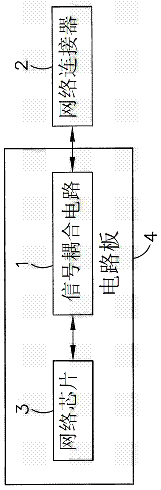
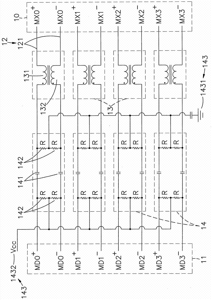
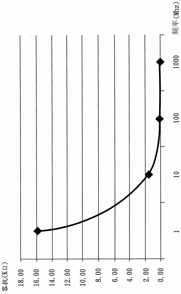
[0052] see Figure 1 to Figure 3 As shown, it is a block diagram of a preferred embodiment of the present invention, a circuit diagram of the signal coupling circuit, a comparison diagram of frequency and capacitive reactance, and it can be clearly seen that the network signal coupling circuit is arranged on the circuit board 4 as shown in the figure The signal coupling circuit 1, and the two ends are respectively electrically connected to the first connection end 10 of the network connector 2 and electrically connected to the second connection end 11 of the network chip 3. The network chip 3 is a current mode chip, so Network chip 3 outputs current to signal coupling circuit 1, and its signal...
PUM
 Abstract
Description
Claims
Application Information