A method for automatically determining indoor antenna requirements and layout based on grid

An indoor antenna and antenna location technology, applied in the field of communication, can solve the problems that the number and placement of antennas cannot be guaranteed, and the workload is heavy, so as to save design labor, avoid investment waste, and improve design efficiency.

Inactive Publication Date: 2016-02-10
GUANGXI CHENGTIAN INFORMATION TECH
View PDF3 Cites 0 Cited by
  • Summary
  • Abstract
  • Description
  • Claims
  • Application Information

AI Technical Summary

Problems solved by technology

However, in this current method, the number of antennas and the optimal position of each antenna are still determined by technicians, and only simulation tools are used to evaluate the wireless signal coverage effect
By manually changing the number and location of antennas deployed many times, the indoor wireless signal coverage effect can be guaranteed to meet the needs of telecom operators. Therefore, this method also has a huge workload, and cannot guarantee the final number and layout of antennas. The location is the best, only to meet the needs of network construction
According to the information consulted by the inventor, there is currently no document that records the method for automatically determining the distribution of indoor antennas.

Method used


Image

  • A method for automatically determining indoor antenna requirements and layout based on grid
  • A method for automatically determining indoor antenna requirements and layout based on grid
  • A method for automatically determining indoor antenna requirements and layout based on grid

Examples


Embodiment

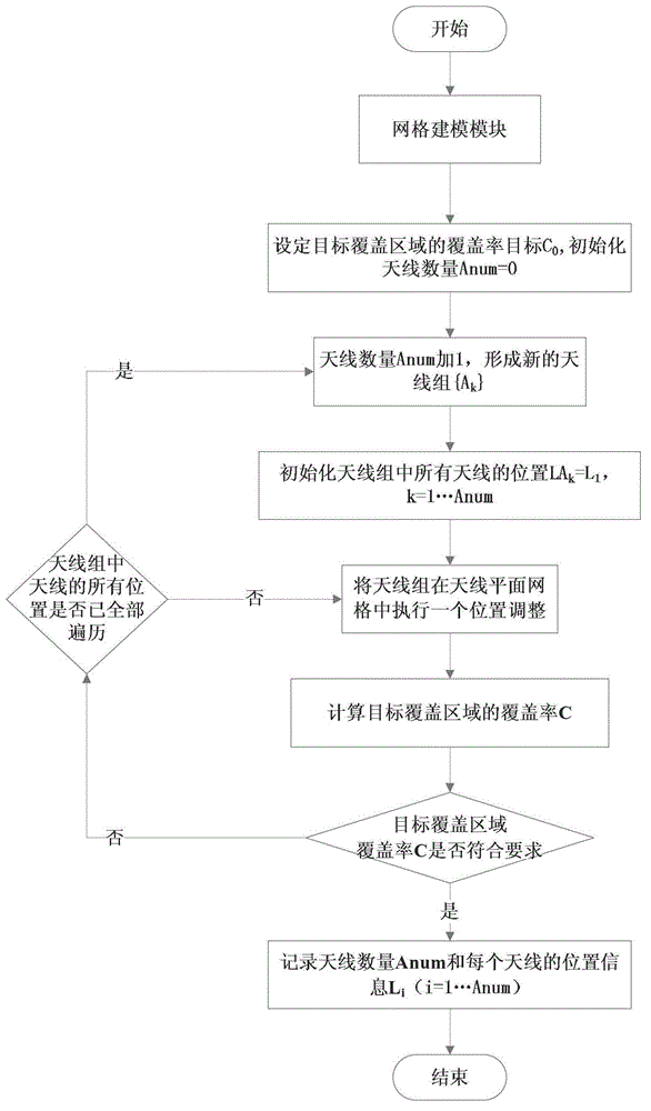
[0054] An antenna position grid and a target user position grid constructed by the grid modeling module, combined with the calculation of the field strength and coverage rate of the target coverage area, and finally automatically determine the one that meets the user coverage requirements after an iterative cycle The method for the number of antennas and the location of each antenna includes the following steps in turn:

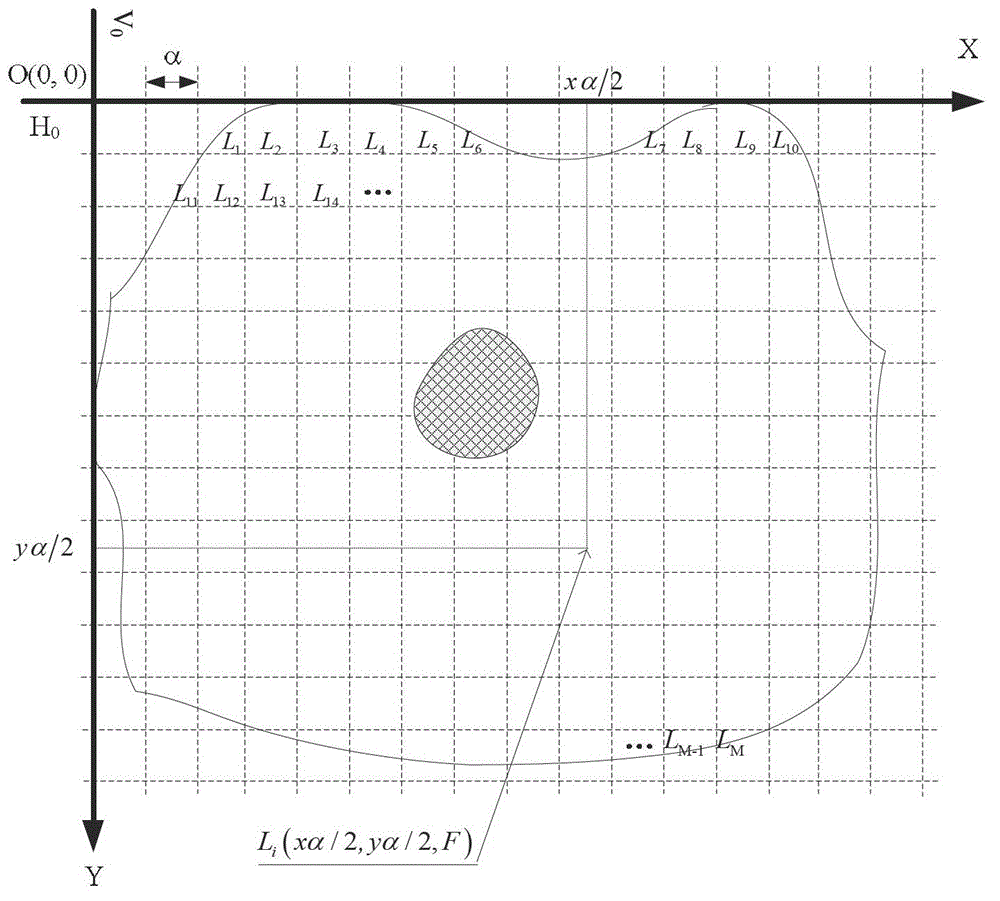
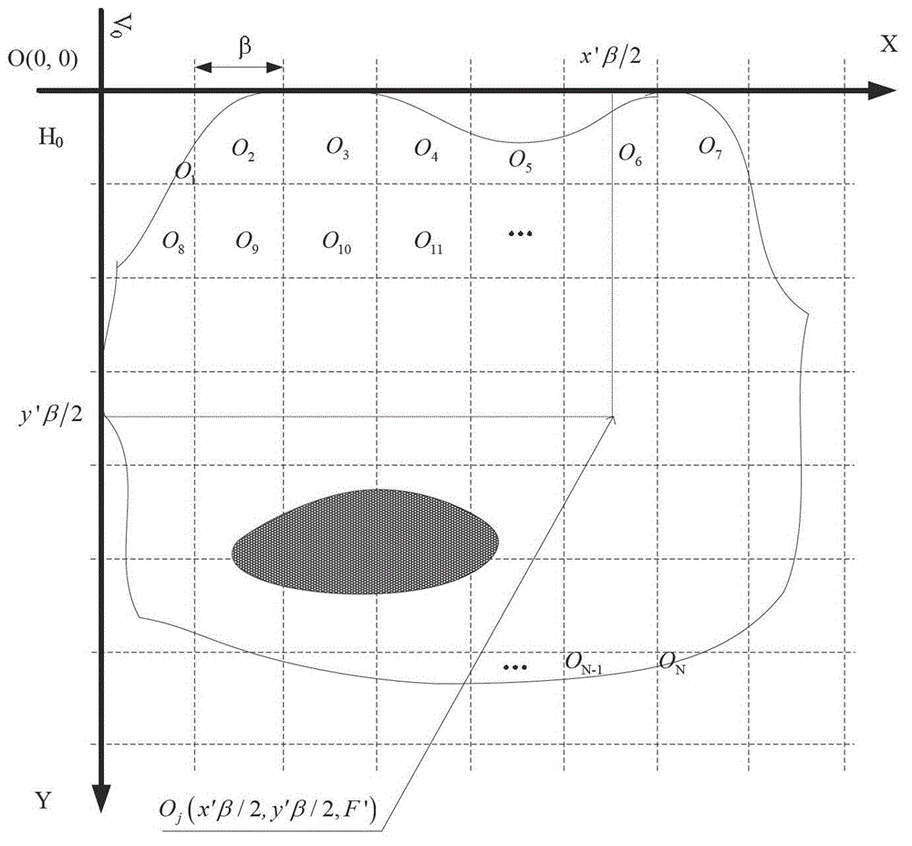
[0055] Step 1, using the grid modeling module to build the antenna position grid on the plane where the indoor antenna is located, and build the target user position grid on the plane of the target coverage area; the antenna position grid is provided with M grids in total, for each Antenna position grids are sequentially numbered as L i ; The target user location grid is provided with N grids in total, and each target user location grid is numbered sequentially as O j ;where i=1,...,M; j=1,...,N; specifically

[0056] 1) In the two-dimensional plane of the ...


PUM


Abstract

The invention discloses a grid-based automatically-determining indoor antenna requirement and arrangement method. The method comprises the following steps: firstly, utilizing a grid modeling module to build antenna position grids and target user location grids; secondly, calculating the field strength and the coverage rate of a target coverage area; finally, automatically determining antenna quantity and antenna positions meeting coverage requirements of users eventually through an iterative loop. The method can automatically determine the minimal antenna quantity and the optimal antenna arrangement positions meeting the requirements of the construction of an indoor wireless network, so that the design efficiency and the quality of an engineering technical worker are improved, design labor is saved, and wasteful investment is avoided; the method is is practical and effective, and easy to realize and popularize.

Description

technical field [0001] The invention belongs to the technical field of communications, and relates to a method for determining the distribution of indoor antennas, in particular to a method for automatically determining the requirements and arrangement of indoor antennas based on gridding. Background technique [0002] Indoor is the main scenario where mobile communication services occur, and the indoor wireless communication network carries most of the user's communication traffic such as voice and data. The signal source of the multi-antenna indoor distribution system is relatively pure, the interference is relatively small, and the signal source power is evenly distributed indoors, which can attract indoor user traffic, so it is currently one of the most important indoor wireless network solutions for telecom operators. [0003] A major issue in the engineering design of indoor distribution systems is how to design the number and location of each antenna in the indoor dis...

Claims


Application Information

Patent Timeline
Patent Type & Authority Patents(China)
IPC IPC(8): H04W16/20
Inventor 尹东彬陈欣
Owner GUANGXI CHENGTIAN INFORMATION TECH
Why Eureka
Try Eureka