Shaft seal apparatus

A technology of shaft sealing and fluid sealing, applied in the direction of engine sealing, engine components, mechanical equipment, etc., can solve the problems of insufficient fluid circulation, insufficient fluid discharge, insufficient fluid discharge force, etc., to improve the discharge pressure, increase the The effect of large fluid discharge and easy cooling

Active Publication Date: 2013-11-13
EAGLE INDS
View PDF5 Cites 11 Cited by
  • Summary
  • Abstract
  • Description
  • Claims
  • Application Information

AI Technical Summary

Problems solved by technology

[0003] However, in the existing shaft sealing device, since the thrust to discharge the sealing fluid from the discharge hole is only the pumping action performed by a part of the impeller, the discharge of the fluid is not sufficient, and the fluid circulation by the pumping function is not sufficient. carried out, it is difficult to cool effectively
Especially when radially extending discharge holes have to be formed instead of axially extending discharge holes, the discharge force of the fluid is insufficient

Method used


Image

  • Shaft seal apparatus
  • Shaft seal apparatus
  • Shaft seal apparatus

Examples


no. 1 approach

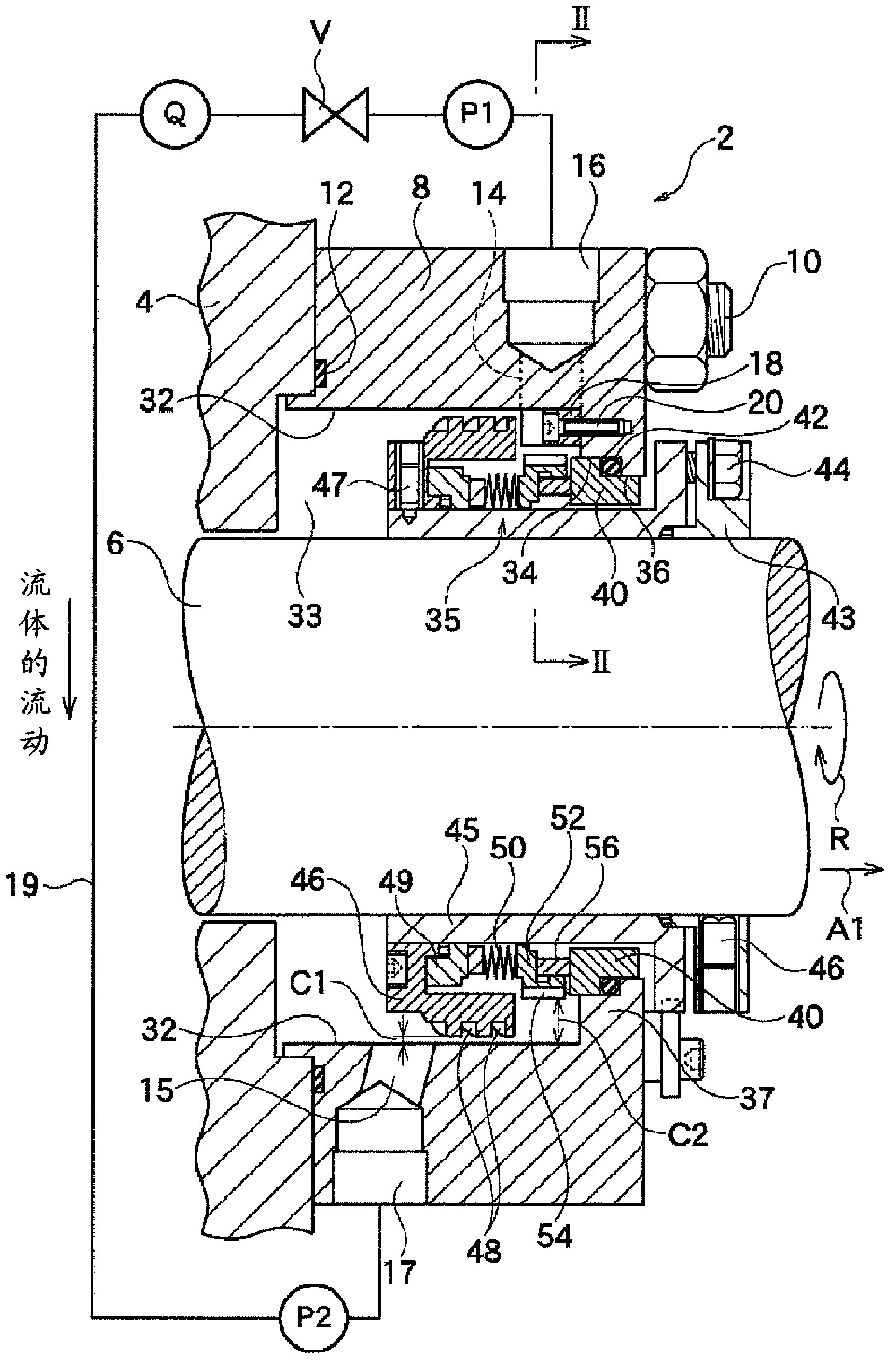
[0062] Such as figure 1 As shown, the shaft sealing device 2 according to one embodiment of the present invention is a device for realizing a fluid seal between a housing (stationary part) 4 and a rotating shaft (rotating body) 6 in a fluid machine such as a pump or a compressor.

[0063] The rotating shaft 6 extends inside the casing 4 , and an impeller (not shown) etc. is attached to the rotating shaft 6 , and the pressure of the processing fluid is controlled inside the casing 4 . The shaft sealing device 2 of this embodiment is configured so that the processing fluid inside the housing 4 does not leak to the outside from the gap between the housing 4 and the rotating shaft 6 at the end of the housing 4 along the rotating shaft 6 . figure 1 Only the shaft sealing device 2 installed on one end of the housing 4 along the rotating shaft 6 is shown in the figure, but there is also a shaft sealing device 2 installed on the other end of the housing 4 along the rotating shaft 6 C...

no. 2 approach

[0100] Figure 8 The other embodiments of the invention shown relate to shaft seals 2b different from figure 1 and Figure 7 The single type mechanical seal shown is a tandem type mechanical seal, and two first and second mechanical seals 35a and 35b are installed in the axial direction. In the following instructions, only the detailed description differs from Figure 1 to Figure 7 For the part of the embodiment shown, description of some common parts will be omitted.

[0101] Such as Figure 8 As shown, in this embodiment, the first sealing cover 8 a is detachably mounted and fixed on the outer end (in the direction of arrow A1 ) of the housing 4 via the second sealing cover 8 b through bolts 10 . The first seal member 12a such as a gasket is sandwiched between the first seal cover 8a and the second seal cover 8b, and the second seal member 12b is sandwiched between the second seal cover 8b and the case 4 to seal the gap between them.

[0102] The same mechanical seal de...


PUM


Abstract

A pumping ring (46), producing an axial flow of a sealed fluid so that a sealed fluid positioned in a sealed space (33) flows along the central axial direction of a rotating shaft (6), is secured to a rotating shaft (6) in an axial position different than a rotating ring (56). A discharge hole (14) is formed in the inner circumferential surface of a seal cover (8) positioned on the downstream side of the axial flow of the sealed fluid resulting from the rotation of the pumping ring (46). An inflow hole (15) is formed in a position on the upstream side of the axial flow of the sealed fluid resulting from the rotation of the pumping ring (46). The configuration is such that sealed fluid discharged from the discharge hole (14) returns to the interior of the sealed space (33) from the inflow hole (15). A rectifying member (18) is provided so as to protrude toward the inside in a radial direction in the inner circumferential surface of the seal cover (8) where the discharge hole (14) is formed. The rectifying member retains the flow of the sealed fluid along the rotational direction of a retainer (52) and orients the sealed fluid toward the discharge hole (14).

Description

technical field [0001] The present invention relates to a shaft sealing device, and more particularly to a shaft sealing device capable of effectively cooling a rotating ring and a stationary ring sliding mutually. Background technique [0002] For example, in a shaft seal constituted by a mechanical seal shown in Patent Document 1 below, a partial impeller for pumping fluid to circulate itself is attached to a rotating shaft. In addition, on the inner peripheral surface of the stuffing box located on the outer periphery of the rotating shaft, inlet holes and outlet holes are provided at positions different from the axial direction. Therefore, the rotation of the rotating shaft generates an axial flow from the inlet hole to the outlet hole, thereby cooling the mechanical seal composed of the rotating ring and the stationary ring. [0003] However, in the existing shaft sealing device, since the thrust to discharge the sealing fluid from the discharge hole is only the pumpin...

Claims


Application Information

Patent Timeline
Patent Type & Authority Applications(China)
IPC IPC(8): F16J15/34
CPCF16J15/3404F16J15/3484F16J15/406
Inventor 泷介平宜昭押井要二金子敦佐藤徹也
Owner EAGLE INDS
Why Eureka
Try Eureka