Simple handheld photoacoustic imaging probe

A photoacoustic imaging and handheld technology, which is applied in medical science, sensors, diagnostic recording/measurement, etc., can solve the problems of no longer applicable detection, high cost, and huge array of ultrasonic probes, and achieve the effect of easy adaptability

Active Publication Date: 2013-11-20
SHENZHEN INST OF ADVANCED TECH
View PDF9 Cites 5 Cited by
  • Summary
  • Abstract
  • Description
  • Claims
  • Application Information

AI Technical Summary

Problems solved by technology

[0008] (1) if figure 1 As shown, the existing design based on optical fiber bundles for oblique irradiation of excitation light from both sides of the handheld ultrasonic probe array has the disadvantage that the photoacoustic signal mainly comes from a specific depth area in the tissue, and the imaging effect on other detection areas of the ultrasonic probe Not ideal; in addition, this design is expensive due to the use of fiber optic bundles for delivery of illumination light and excitation of the sample
[0009] (2) if figure 2 As shown, the existing hand-held ultrasonic probe array coupling module irradiates the sample with light from directly below the ultrasonic probe perpendicular to the probe. The disadvantage is that the ultrasonic probe array becomes huge and is no longer suitable for armpit and crotch, etc. area detection; in addition, this design may have adaptability problems for the operator

Method used


Image

  • Simple handheld photoacoustic imaging probe
  • Simple handheld photoacoustic imaging probe
  • Simple handheld photoacoustic imaging probe

Examples


Embodiment Construction

[0047] In order to make the object, technical solution and advantages of the present invention clearer, the present invention will be further described in detail below in conjunction with the accompanying drawings and embodiments. It should be understood that the specific embodiments described here are only used to explain the present invention, not to limit the present invention.

[0048] In addition, the technical features involved in the various embodiments of the present invention described below can be combined with each other as long as they do not constitute a conflict with each other.

[0049] The ultrasonic probe in this embodiment is a hand-held ultrasonic probe.

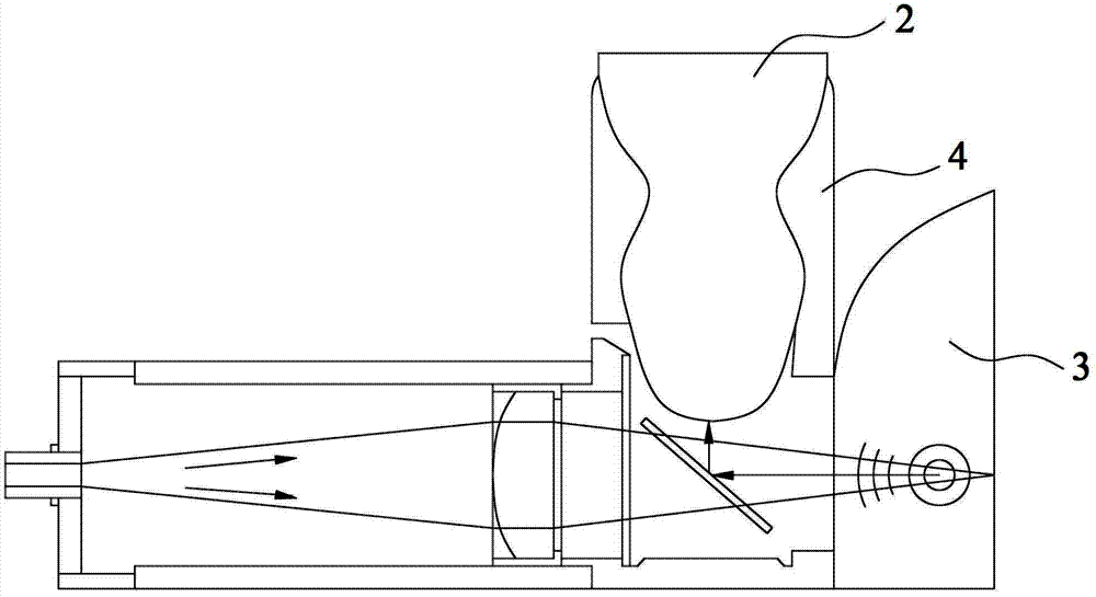
[0050] For the directions of up, down, left and right mentioned below, unless otherwise specified, please refer to the attached image 3 orientation shown.

[0051] Figure 3-Figure 5 In , the slash-filled areas represent rays.

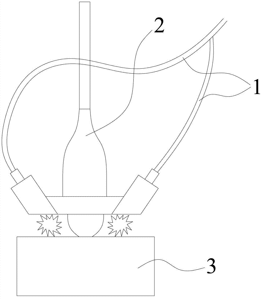
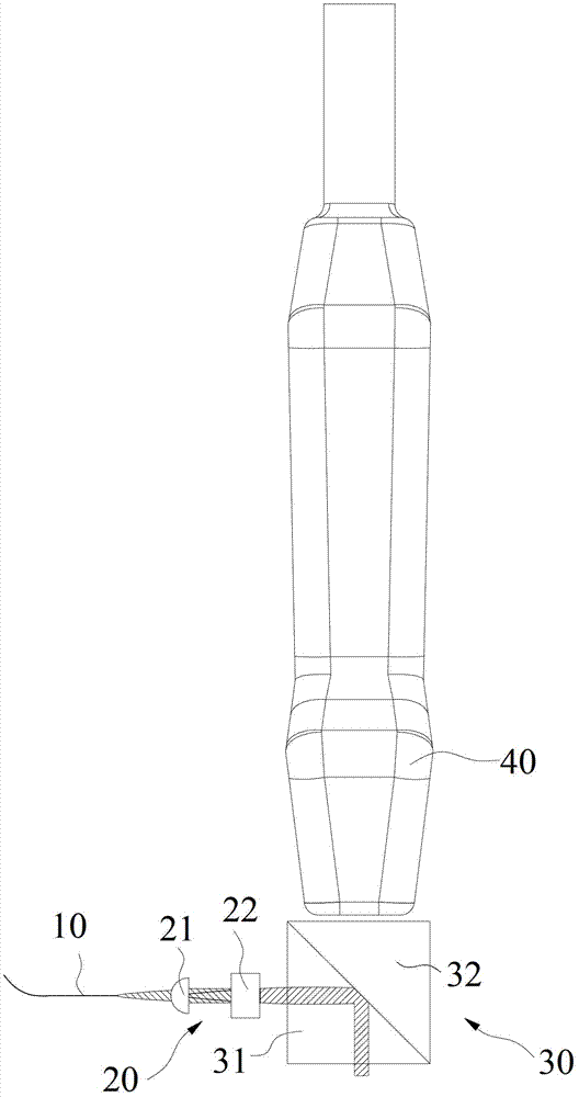
[0052] Such as Figure 3-Figure 5 As shown, a schematic diagram of the s...


PUM


Abstract

The invention relates to the technical field of photoacoustic imaging and provides a simple handheld photoacoustic imaging probe. Exciting light is coupled into an optical fiber (10); light from the optical fiber (10), in a direction parallel to the surface of an object to be tested, is focused by a spatial expansion and lens group (20) before entering a coupling module (30); the light entering the coupling module (30) is totally reflected by a position, right below an ultrasonic probe (40), corresponding to an ultrasonic probe detection area of the object to be tested and vertically irradiates to the ultrasonic probe detection area of the object to be tested, right below the ultrasonic probe (40), so as to excite a photoacoustic signal; the photoacoustic signal is transmitted into the coupling module (30) through the ultrasonic probe detection area of the object to be tested, and the ultrasonic probe (40) receives the photoacoustic signal. The simple handheld photoacoustic imaging probe has the advantages that the exiting light irradiation area and the ultrasonic probe detection area are allowed to overlap without significantly increasing the size of the ultrasonic probe; the ultrasonic probe is kept traditionally be perpendicular to the object to be tested and is easy for an operator to adapt to.

Description

【Technical field】 [0001] The invention relates to the technical field of photoacoustic imaging, in particular to a simple hand-held photoacoustic imaging probe. 【Background technique】 [0002] Optical imaging technology is one of the most rapidly developing branches of various biomedical imaging technologies. Compared with other medical imaging methods such as X-ray imaging, computed tomography, positron emission tomography, ultrasound imaging, magnetic resonance imaging, etc., optical imaging technology has one or more advantages in resolution, chemical specificity, sensitivity, safety, etc. Each has advantages. However, the biggest limitation of optical imaging technology lies in its tissue penetration depth, and the emergence of photoacoustic imaging technology has overcome this defect well. Photoacoustic imaging has the advantages of both optical resolution and acoustic imaging depth. It uses the optical absorption characteristics of tissues as a contrast mechanism to ...

Claims


Application Information

Patent Timeline
Patent Type & Authority Applications(China)
IPC IPC(8): A61B5/00
Inventor 宋亮刘成波白晓淞林日强
Owner SHENZHEN INST OF ADVANCED TECH
Why Eureka
Try Eureka