Lateral flow chip and its joint device
A technology of a joint device and a flow chip, which is applied to laboratory utensils, laboratory containers, chemical instruments and methods, etc., can solve the problems of complicated operation, difficult to popularize the microfluidic chip, and the chip joint device cannot be reused. , to achieve the effect of easy operation
- Summary
- Abstract
- Description
- Claims
- Application Information
AI Technical Summary
Problems solved by technology
Method used
Image

Examples
Embodiment 1
[0016] Example 1 A microfluidic chip and its joint device based on the side hook structure
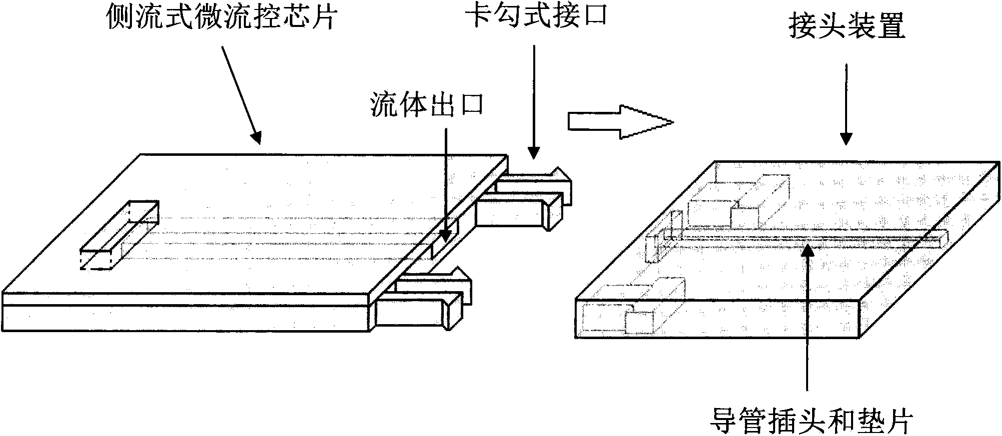
[0017] The invention provides a microfluidic chip and a joint device thereof, the structure of which is as follows: figure 1 As shown, the microfluidic chip has at least one fluid outlet located on the side wall of the chip; hooks are processed on the fluid outlet surface of the chip; the joint device consists of an elastic gasket, a catheter plug and a shell with a buckle structure.
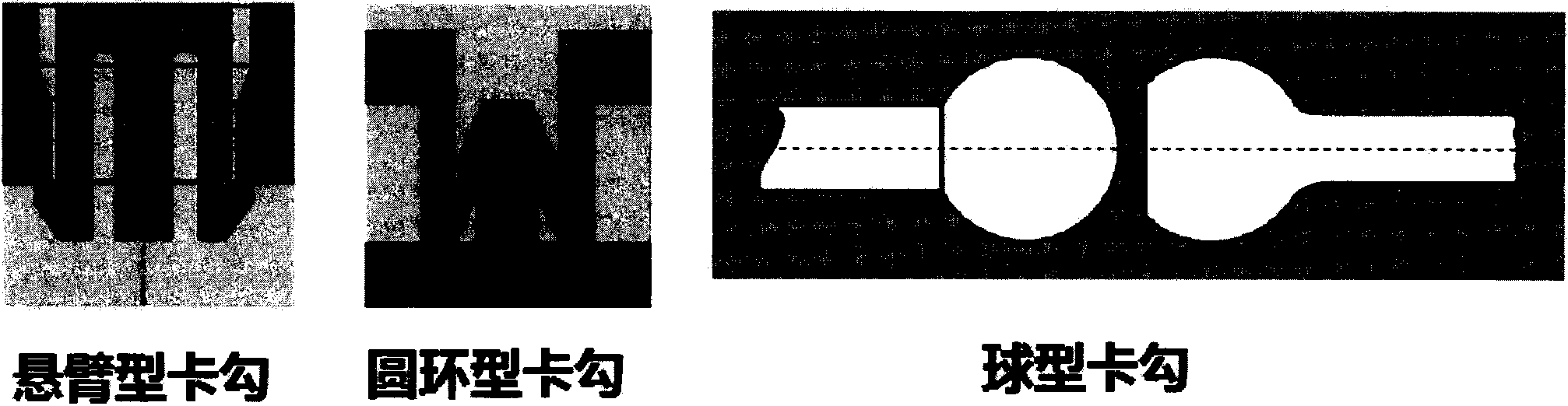
[0018] More specifically, the buckle structure can be as figure 2 The three structures shown in , for example: cantilever type hook, ring type hook, ball type hook. That is, the hook on the microfluidic chip can be cantilever-shaped, circular-shaped or spherical-shaped, and the shell on the corresponding joint device is processed with a structure that complements it and can be locked tightly.
[0019] When in use, align the hook of the above-mentioned microfluidic chip with the slot of the shell and t...
Embodiment 2
[0020] Example 2 A microfluidic chip and its joint device based on the surface spherical hook structure
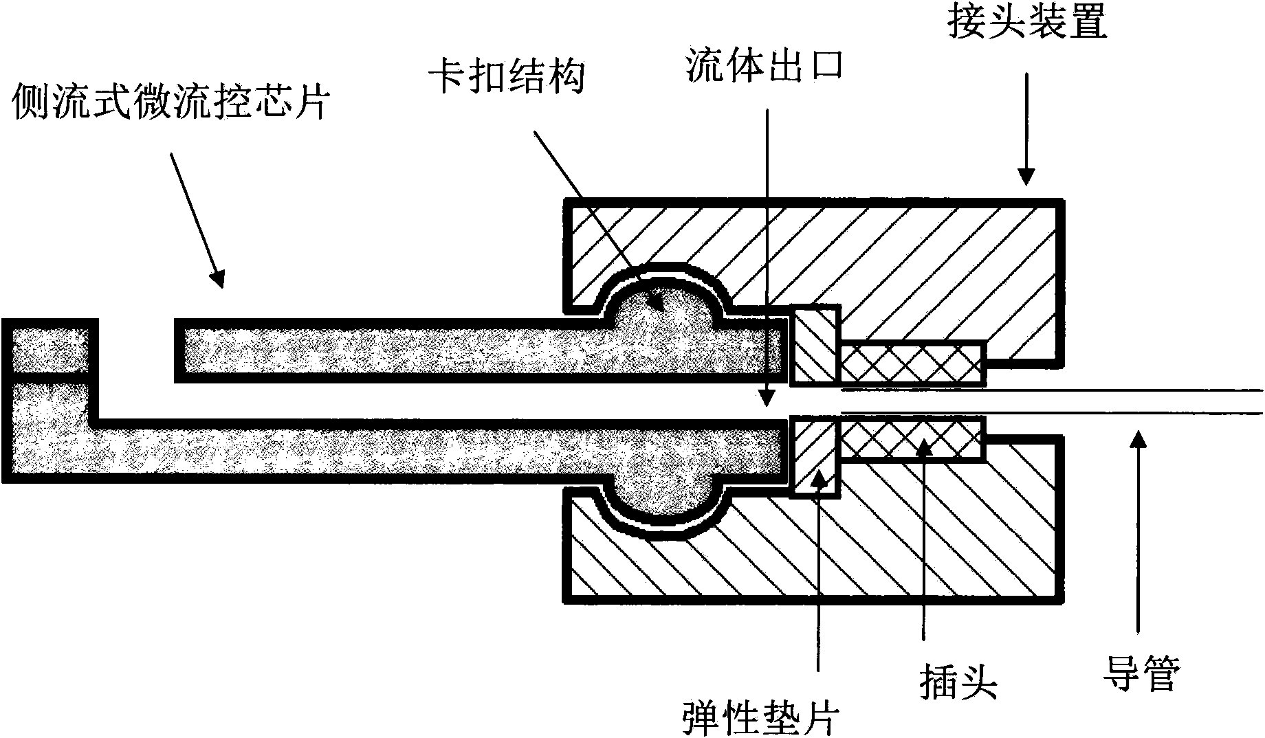
[0021] The invention provides a microfluidic chip and a joint device thereof, the structure of which is as follows: image 3 As shown, the microfluidic chip has at least one fluid outlet located on the side wall of the chip; the top and bottom of the chip are processed with spherical structures; the joint device consists of an elastic gasket, a catheter plug and a shell with a buckle structure.
[0022] When in use, align the hook of the above-mentioned microfluidic chip with the slot of the housing and insert it, then the spherical structure and the buckle structure in the joint device will be tightly locked, thereby realizing the fluid outlet of the microfluidic chip and the joint device. The elastic gasket is tightly fixed; the catheter connected to the external pump valve system or pipetting system is connected to the catheter plug, and finally the connection between t...
PUM
 Abstract
Description
Claims
Application Information
 - R&D
- Intellectual Property
- Life Sciences
- Materials
- Tech Scout
- Unparalleled Data Quality
- Higher Quality Content
- 60% Fewer Hallucinations
Browse by: Latest US Patents, China's latest patents, Technical Efficacy Thesaurus, Application Domain, Technology Topic, Popular Technical Reports.
© 2025 PatSnap. All rights reserved.Legal|Privacy policy|Modern Slavery Act Transparency Statement|Sitemap|About US| Contact US: help@patsnap.com