
Automatic material distribution machine

An automatic splitting machine and driving mechanism technology, which is applied in the field of casting splitting, can solve the problems of complex structure of the manipulator, inability to realize splitting operation, inconvenient operation, etc., and achieve the effect of saving cooling processing mechanism, less damage to the workpiece, and less damage

Active Publication Date: 2013-11-20
吴芳艺
View PDF6 Cites 9 Cited by
  • Summary
  • Abstract
  • Description
  • Claims
  • Application Information

AI Technical Summary

Problems solved by technology

In addition, in the pickling method disclosed in patent application number 201210251955.5, the structure of the manipulator is extremely complicated, the operation is inconvenient, and the material can only be broken horizontally, while the workpieces on the casting are usually arranged in both horizontal and vertical directions. The workpiece, the manipulator structure is unable to realize the material breaking operation

Method used


Image

  • Automatic material distribution machine
  • Automatic material distribution machine
  • Automatic material distribution machine

Examples


Embodiment Construction

[0063] The present case will be described in further detail below in conjunction with the accompanying drawings and specific embodiments.

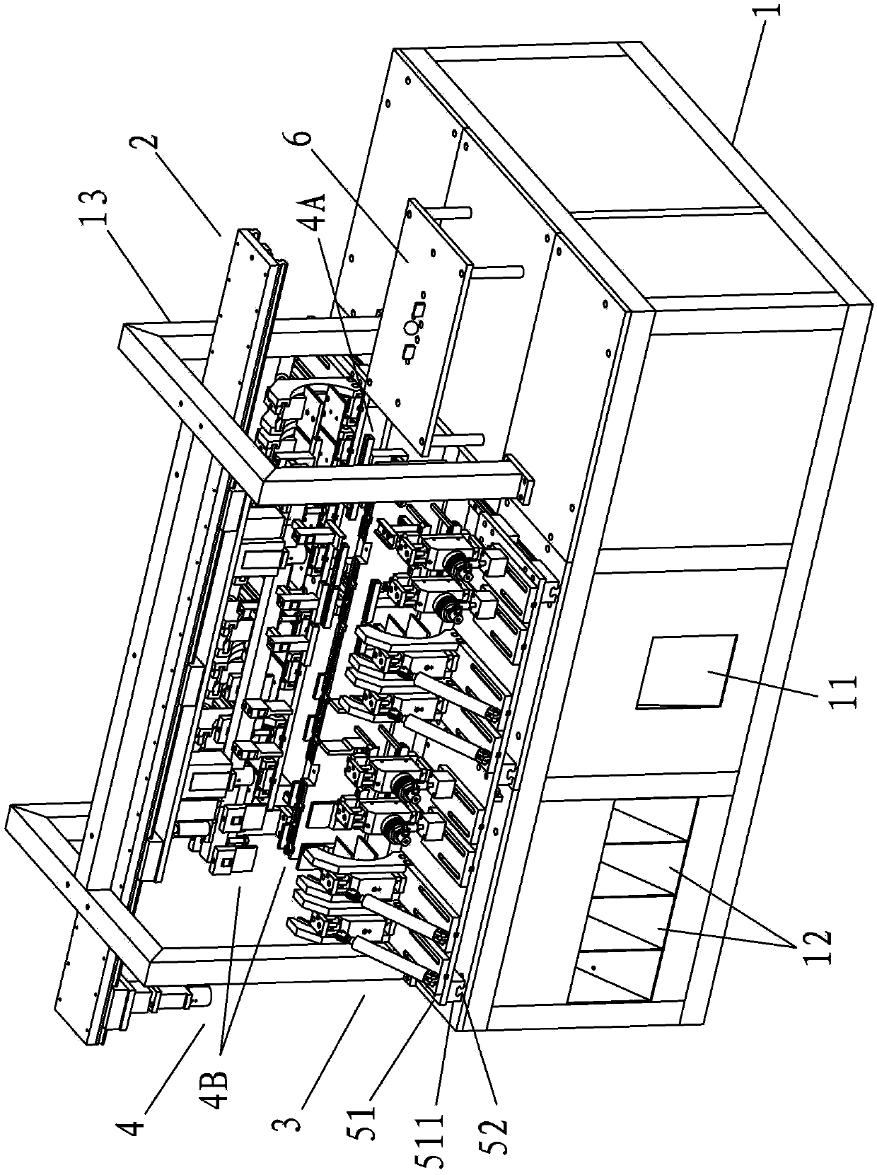
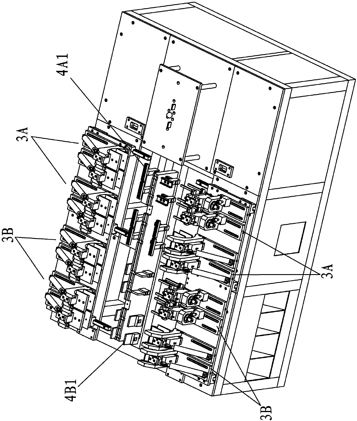
[0064] The present invention relates to a kind of automatic distributing machine, such as Figure 1-10 As shown, it mainly includes a main body 1 , a conveying device 2 , a manipulator device 3 and a pressing device 4 . Such as Figure 11 Shown is a schematic structural view of the existing casting 7 , including a flow channel body 71 , a workpiece 72 and a discharge material 73 . The workpieces 72 are divided into four groups and connected to the four branches of the flow channel body 71 , and the overflow material 73 corresponds to four groups, which are respectively connected to the four groups of workpieces 72 . Figure 11 Among them, the workpiece 72 has two kinds of arrangement structures, horizontal and vertical, and the corresponding overflow material 73 also has two kinds of arrangement structures, horizontal and vertical.

[0...


PUM


Abstract

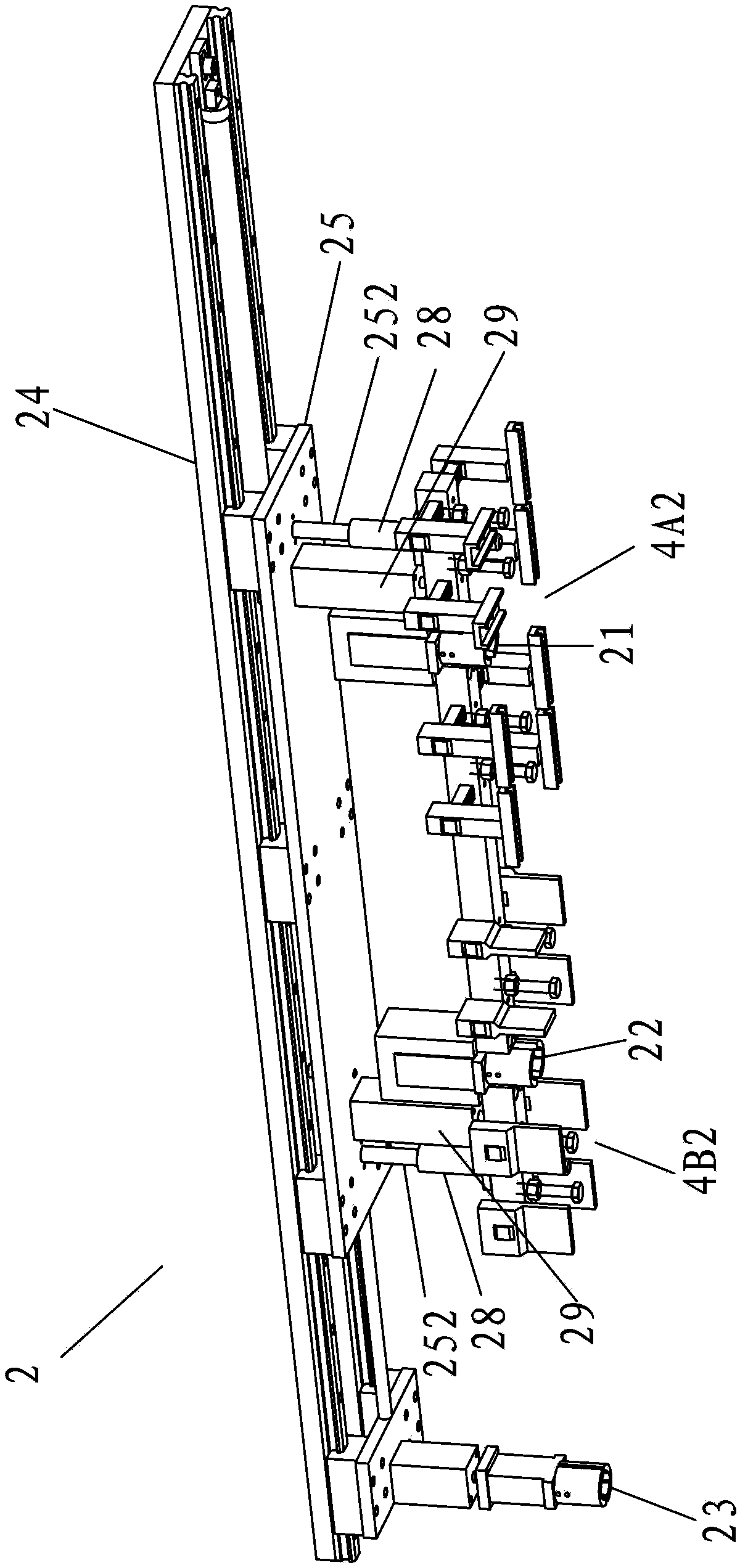
The invention discloses an automatic material distribution machine. The automatic material distribution machine mainly comprises a main machine body, a transporting device, a mechanical arm device and a pressing device. The mechanical arm device comprises first mechanical arm device bodies and second mechanical arm device bodies. The transporting device is arranged above the mechanical arm device. The transporting device comprises first pneumatic fingers, second pneumatic fingers and a third pneumatic finger, wherein the first pneumatic fingers and the second pneumatic fingers are respectively arranged in parallel in a left and right mode and can respectively and synchronously move left and right and respectively and synchronously move up and down. The pressing device comprises a first pressing device body and a second pressing device body, wherein the first pressing device body and the second pressing device body are arranged in parallel in a left and right mode. The first pressing device body comprises first upper pressing device main bodies and first lower pressing device main bodies, wherein the first upper pressing device main bodies are correspondingly matched with each other and can move downward, and the first lower pressing device main bodies are arranged between the two sets of first mechanical arm device bodies. The second pressing device comprises second upper pressing device main bodies and second lower pressing device main bodies, wherein the second upper pressing device main bodies are correspondingly matched with each other and can move downward, and the second lower pressing device main bodies are arranged between the two sets of second mechanical arm device bodies. The automatic material distribution machine is simple in structure, free of a cooling device, good in material distributing effect, and extremely high in automatic degree and efficiency.

Description

technical field [0001] The invention relates to the technical field of casting material distribution, in particular to an automatic material distribution machine. Background technique [0002] In the production of castings, die-casting is performed by a die-casting machine. Each mold usually includes several workpieces. The several workpieces are connected together through the runner body, and redundant discharge material is connected to the outside of each workpiece. To obtain a single-piece finished workpiece, each workpiece needs to be separated from the runner body and the flash drain. Traditionally, the separation of workpieces is done manually, and the casting is repeatedly bent by hand, which has the disadvantages of high labor intensity and low work efficiency. [0003] In the prior art, some people propose to use mechanical methods instead of manual methods. For example, stamping processing methods are used. Although this method avoids the problem of manual high-st...

Claims


Application Information

Patent Timeline
Patent Type & Authority Applications(China)
IPC IPC(8): B22D17/20B22D29/04
Inventor 吴芳艺
Owner 吴芳艺
Learn More