
Belt wheel press assembling device and press assembling method

A press-fitting device and pulley technology, applied in metal processing, metal processing equipment, manufacturing tools, etc., can solve the problems of high labor intensity, easy fatigue, low production efficiency, etc., and achieve high operating efficiency, simple device structure, and method easy effect

Active Publication Date: 2013-11-20
GUANGXI YUCHAI MASCH CO LTD
View PDF7 Cites 14 Cited by
  • Summary
  • Abstract
  • Description
  • Claims
  • Application Information

AI Technical Summary

Problems solved by technology

[0002] During engine assembly, such as figure 1 As shown, the assembly process requires that the pulley b and the small diameter end shaft end a1 of the crankshaft a of the engine are assembled by interference fit, and an assembly tool is required to install the pulley b on the small diameter end shaft end a1. At present, there is no special assembly tool for assembly. Drive the pulley into the crankshaft small-diameter end shaft head with a hammer and a beating tool. When beating, pre-install the pulley b on the small-diameter end shaft head a1 of the crankshaft, hold the beating tool, and put one end of the beating tool close to the pulley b. Manually The hammer hits the other end of the beating tool, and repeatedly hits until the pulley b is driven into the shaft head a1 of the small diameter end of the crankshaft. Since both the hammer and the beating tool are fixed manually, it is easy to cause fatigue during beating, and there are also There is a potential safety hazard when hitting the hand. At the same time, other parts of the engine will vibrate during the hammering process, which will affect the assembly quality of the engine. The existing assembly method has the defects of high labor intensity and low production efficiency.

Method used


Image

  • Belt wheel press assembling device and press assembling method
  • Belt wheel press assembling device and press assembling method
  • Belt wheel press assembling device and press assembling method

Examples


Embodiment Construction

[0025] The specific embodiments of the present invention will be described in detail below in conjunction with the accompanying drawings, but it should be understood that the protection scope of the present invention is not limited by the specific embodiments.

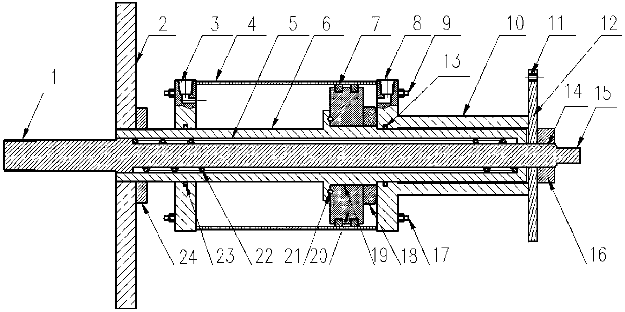
[0026] Such as figure 2 As shown, first introduce the structure and working principle of the belt pulley press-fitting device. The device includes a screw rod 15, a piston rod 6, a pressure plate 2 and a telescopic drive part; the piston rod 6 is sleeve-shaped, sleeved on the screw rod 15 and Move on the screw rod 15 under the action of the telescopic driving part; the pressure plate 2 is fixed on one end of the piston rod 6; The external thread 1 matched with the thread hole on the end surface of the crankshaft head where the pulley is installed, the telescopic drive part has a fixed end and a telescopic end, the fixed end is in contact with the end of the screw rod 15 away from the pressure plate 2, that is, the rea...


PUM


Abstract

The invention discloses a belt wheel press assembling device and a press assembling method. The device comprises a screw rod, a piston rod, a pressure plate and a telescopic drive component. The piston rod is in a sleeve shape, is arranged on the screw rod in a sleeved mode and can move on the screw rod under the action of the telescopic drive component. The pressure plate is fixed at one end of the piston rod. The two ends of the screw rod extend out of the piston rod outwards in a hanging mode. The end, close to the pressure plate, of the screw rod is provided with an external thread matched with a screw hole formed in the shaft head end face of a crankshaft and used for installing a belt wheel. The telescopic drive component has a fixed end and a telescopic end, wherein the fixed end is fixed at the end, away from the pressure plate, of the screw rod, and the telescopic end is fixed to the piston rod or the pressure plate. In the installation process, what is needed is to control stretching and contracting of the telescopic drive component, assembling of the belt wheel can be completed, the telescopic drive component can be a hydraulic oil cylinder, an air cylinder or other mechanical telescopic mechanisms, vibration influence on other assembled components of an engine is little, compared with manual hitting, labor intensity is greatly reduced, and assembling efficiency is improved.

Description

technical field [0001] The invention relates to an engine assembly technology, in particular to a belt pulley press-fitting device and a press-fitting method. Background technique [0002] During engine assembly, such as figure 1 As shown, the assembly process requires that the pulley b and the small diameter end shaft end a1 of the crankshaft a of the engine are assembled by interference fit, and an assembly tool is required to install the pulley b on the small diameter end shaft end a1. At present, there is no special assembly tool for assembly. Drive the pulley into the crankshaft small-diameter end shaft head with a hammer and a beating tool. When beating, pre-install the pulley b on the small-diameter end shaft head a1 of the crankshaft, hold the beating tool, and put one end of the beating tool close to the pulley b. Manually The hammer hits the other end of the beating tool, and repeatedly hits until the pulley b is driven into the shaft head a1 of the small diameter...

Claims


Application Information

Patent Timeline
IPC IPC(8): B23P19/027
Inventor 朱茂保谭伟权黎雪清杨业培陈峰
Owner GUANGXI YUCHAI MASCH CO LTD
Features
  • Generate Ideas
  • Intellectual Property
  • Life Sciences
  • Materials
  • Tech Scout
  • Unparalleled Data Quality
  • Higher Quality Content
  • 60% Fewer Hallucinations
Learn More