
Formwork panel dismountable and thickness adjustable combined steel bar truss floor bearing plate

A reinforced truss, combined technology, applied in the direction of formwork/formwork/work frame, formwork/formwork/work frame connector, formwork treatment, etc., can solve the problems of waste of labor, damage, waste, etc. Broad market prospects, easy installation and disassembly, and reduced production costs

Active Publication Date: 2015-06-17
NANTONG CONSTR PROJECT GENERAL CONTRACTING
View PDF9 Cites 6 Cited by
  • Summary
  • Abstract
  • Description
  • Claims
  • Application Information

AI Technical Summary

Problems solved by technology

However, because the bottom is supported by thin steel plates, for buildings with suspended ceiling requirements, the galvanized formwork does not need to be removed after the construction is completed, and is directly hidden in the suspended ceiling; for residential buildings without suspended ceilings, after the construction of the floor slab, the steel bars need to be manually destroyed For the solder joints between the truss and the galvanized formwork, remove the galvanized formwork supporting the concrete, and the removed formwork has been severely damaged during the process of destroying the solder joints and separating from the cast-in-place concrete and cannot be reused, that is, waste Labor and waste of cost
[0004] The utility model patent (application number 201220526189.4) proposes a prefabricated reinforced truss floor deck, which can solve the problem of waste of thin steel plates caused by reinforced truss floor slabs
[0005] Based on the above considerations, a combined reinforced truss floor slab with detachable formwork panels and adjustable thickness is proposed. Detachable, easy to use, suitable for various forms of formwork such as plywood, thin steel plate, thick steel plate, etc., which solves the problems of large amount of labor and serious waste of concrete floor slab formwork

Method used


Image

  • Formwork panel dismountable and thickness adjustable combined steel bar truss floor bearing plate
  • Formwork panel dismountable and thickness adjustable combined steel bar truss floor bearing plate
  • Formwork panel dismountable and thickness adjustable combined steel bar truss floor bearing plate

Examples


Embodiment Construction

[0033] The present invention will be further described below in conjunction with the accompanying drawings.

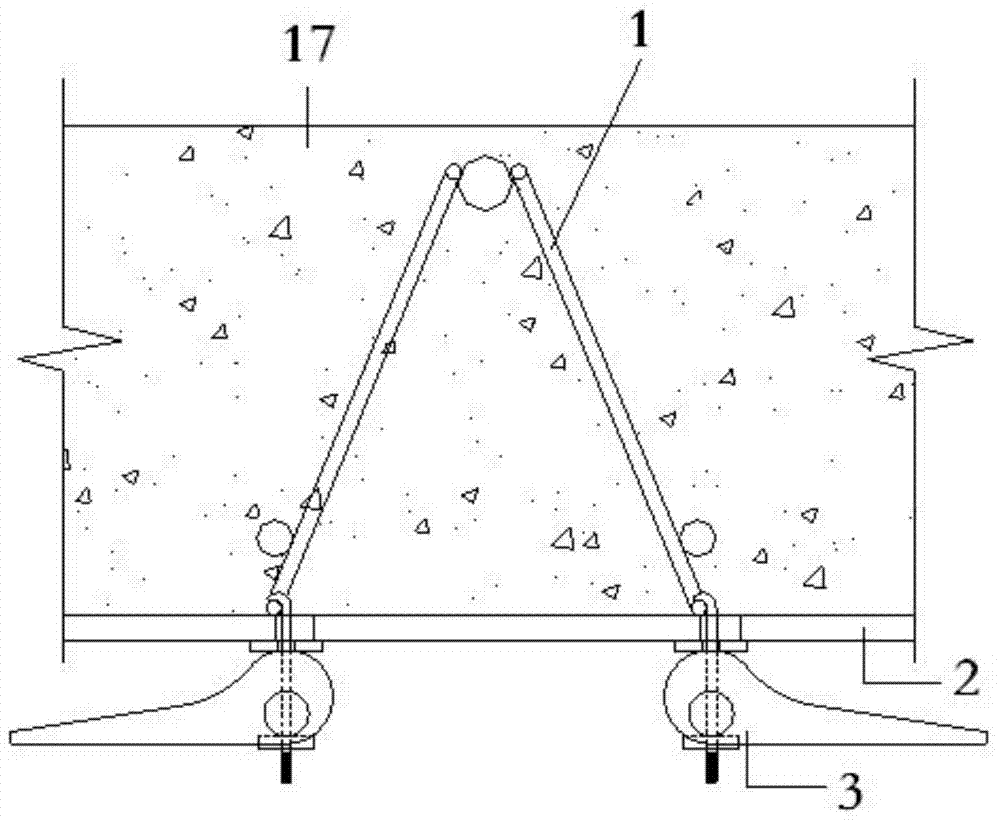
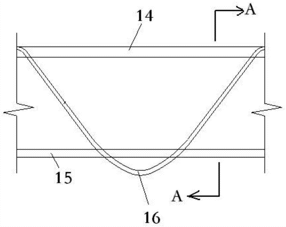
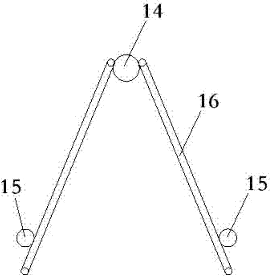
[0034] like Figure 1-8 As shown, a combined steel bar truss floor deck with detachable formwork panels and adjustable thickness, including: steel bar trusses 1, formwork panels 2 and supporting fasteners 3, characterized in that: the formwork panels 2 are provided with several The first through hole 4, the support fastener 3 passes through the first through hole 4 to connect the steel bar truss 1 and the template panel 2, the support fastener 3 includes a hook head 5, a support pad with holes 6. Connecting screw 7, adjusting nut 8, perforated force transmission steel shaft 9 and support wrench 10, the hook head 5 is connected to the top end of the connecting screw 7, the support wrench 10 includes an installation head 11 and a handle 12, the installation The head 11 and the handle 12 are seamlessly connected, and the installation head 11 is provided with a second thr...


PUM


Abstract

The invention discloses a formwork panel dismountable and thickness adjustable combined steel bar truss floor bearing plate which comprises a steel bar truss (1), a formwork panel (2) and bearing fasteners (3), and is characterized in that the bearing fasteners (3) comprise hook heads (5), hole bearing pads (6), connecting screw rods (7), adjusting nuts (8), hole force transmission steel shafts (9) and bearing spanners (10). According to the formwork panel dismountable and thickness adjustable combined steel bar truss floor bearing plate, the formwork panel is free from a welding point, and the floor bearing plate is free from deformation, is convenient to mount and dismount, can be used repeatedly, is suitable for the formwork panels in various types and with different thicknesses, lowers the production cost effectively, and has a broad market prospect.

Description

technical field [0001] The invention relates to a combined reinforced truss floor slab with detachable template panels and adjustable thickness, which is suitable for on-site pouring or factory prefabrication of concrete floor slabs in construction engineering, and belongs to the technical field of building components. Background technique [0002] At present, most of the formwork supports for concrete floor slabs are loose-branched and dismantled formwork systems, including vertical support systems, square corrugated panels, and formwork panels. The commonly used forms of vertical support systems include fastener steel pipes, independent steel supports, etc. . This kind of formwork support method consumes a lot of materials and wastes a lot. It requires a lot of labor during installation, and the construction is cumbersome and the cycle is long. The wooden beams (large and small corrugated) used to support the formwork panels also cause a lot of waste of wood, which does n...

Claims


Application Information

Patent Timeline
Patent Type & Authority Patents(China)
IPC IPC(8): E04B5/32E04G11/36E04G17/00E04G17/04E04G19/00E04G21/00
Inventor 张军陈耀钢王永泉
Owner NANTONG CONSTR PROJECT GENERAL CONTRACTING
Learn More