Gas well liquid-carrying mechanism visualization simulation experiment device of complex structural well

A technology that simulates experimental devices and complex structures. It is used in construction and other directions. It can solve the problems of single linear injection of liquid and lack of extensiveness, and achieve the effect of accurate results.

Inactive Publication Date: 2013-11-20
SOUTHWEST PETROLEUM UNIV
View PDF5 Cites 27 Cited by
  • Summary
  • Abstract
  • Description
  • Claims
  • Application Information

AI Technical Summary

Problems solved by technology

However, in the current experimental plan, the horizontal pipe section of the horizontal well is a straight pipe, and the liquid injection is only a single straight line injection, which is too idealistic and far from the actual situation, and the conclusions made are not universal.

Method used


Image

  • Gas well liquid-carrying mechanism visualization simulation experiment device of complex structural well

Examples


Embodiment 1

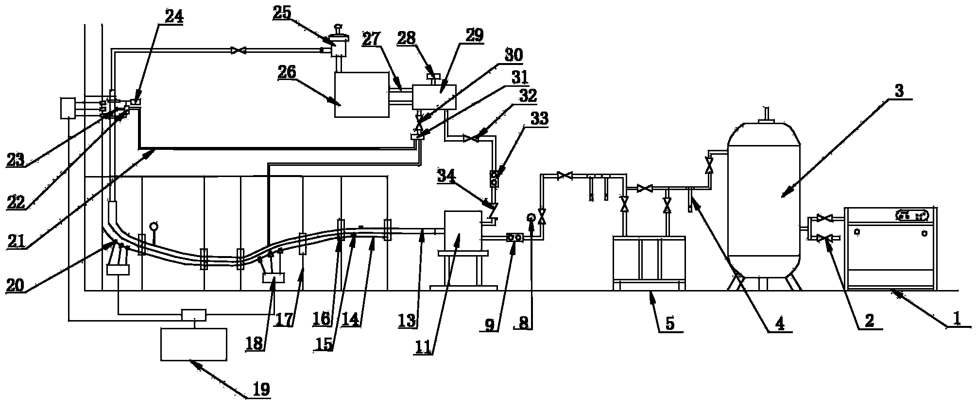
[0020] Embodiment 1, before the experiment starts, the first liquid throttling valve 30 and the second liquid throttling valve 32 are closed. At the beginning of the experiment, the air compressor 1 injects compressed gas into the air storage tank 3, and the compressor 1 and the air storage tank 3 are a linkage device, that is, when the pressure of the air storage tank 3 is lower than the set value, the compressor 1 will automatically turn on the air storage tank 3. The air tank 3 replenishes the air to ensure the stability of the experimental air source. The pressure used in the experiment can be recorded by the pressure gauge 8, and the experimental gas flow rate can be measured by the gas flow meter 9. Turn on the booster pump 29 to adjust the pressure to the pressure required for the experiment. Open the intake throttle valve to inject gas into the wellbore. The pressure of the injected gas can be changed by adjusting the intake throttle valve. The liquid throttling val...

Embodiment 2

[0021] Example 2, before the start of the experiment, adjust the height of each section of the horizontal section to keep it basically level. The first liquid throttle valve 30 and the second liquid throttle valve 32 are closed. At the beginning of the experiment, the air compressor 1 injects compressed gas into the air storage tank 3, and the compressor 1 and the air storage tank 3 are a linkage device, that is, when the pressure of the air storage tank 3 is lower than the set value, the compressor 1 will automatically turn on the air storage tank 3. The gas tank 2 replenishes the gas to ensure the stability of the experimental gas source. The pressure used in the experiment can be recorded by the pressure gauge 8, and the experimental gas flow rate can be measured by the gas flow meter 9. Turn on the booster pump 29 to adjust the pressure to the pressure required for the experiment. Open the intake throttle valve and inject gas into the wellbore. The pressure of the injec...

Embodiment 3

[0022]Embodiment 3, before the start of the experiment, adjust the height of each section of the horizontal section to maintain a certain inclination angle between each section. Close the first liquid throttle valve 30 and the second liquid throttle valve 32 . At the beginning of the experiment, the air compressor 1 injects compressed gas into the air storage tank 3, and the compressor 1 and the air storage tank 3 are a linkage device, that is, when the pressure of the air storage tank 3 is lower than the set value, the compressor 1 will automatically turn on the air storage tank 3. The gas tank 2 replenishes the gas to ensure the stability of the experimental gas source. The pressure used in the experiment can be recorded by the pressure gauge 8, and the experimental gas flow rate can be measured by the gas flow meter 9. Turn on the booster pump 29 to adjust the pressure to the pressure required for the experiment. Open the intake throttle valve and inject gas into the well...


PUM


Abstract

The invention discloses a gas well liquid-carrying mechanism visualization simulation experiment device of a complex structural well. The gas well liquid-carrying mechanism visualization simulation experiment device solves the problem that a simulation experiment is inaccurate, and comprises a gas injection system, a water injection system and a well shaft portion. The gas injection system comprises an air compressor, a gas storage tank and a refrigerated dryer. The air compressor, the gas storage tank and the refrigerated dryer are sequentially communicated. The water injection system comprises a gas-liquid separator, a water storage tank, a booster pump, a pulse ejector and a liquid flow meter. The well shaft portion comprises a well shaft, a gas-liquid mixer and a flow guiding flexible pipe. According to the gas well liquid-carrying mechanism visualization simulation experiment device of the complex structural well, the vertical well gas well liquid-carrying theory can be independently studied, the horizontal-section liquid-carrying theory can be independently studied, a gas well liquid-carrying experiment can be performed, the gas-liquid mixed-phase flow experiment can also be performed, the effect simulated by the device is similar to the practical situation, the results obtained by the experiments are more accurate, and therefore the performed experiments are of great guiding significance in practical production.

Description

technical field [0001] The invention relates to the field of gas liquid-carrying simulation devices, in particular to a visual simulation experiment device for the liquid-carrying mechanism of gas wells with complex structures and accurate simulation tests. Background technique [0002] The production of natural gas is often accompanied by the production of liquids, which are mainly formation water and condensate oil. These liquids downhole may be carried out by the high-speed flowing natural gas, and may also be deposited in the well to form bottomhole fluid accumulation. Natural gas wells will have the problem of bottomhole fluid accumulation. For high-yield gas wells, it often occurs in the middle and late stages. For the large number of "three low" (low permeability, low pressure and low production) gas fields in China, bottomhole fluid accumulation may occur in the early stage of production. Bottomhole fluid accumulation is more harmful and is the main obstacle to natu...

Claims


Application Information

Patent Timeline
Patent Type & Authority Applications(China)
IPC IPC(8): E21B47/002
Inventor 吴锋李溢龙曹丽娜李晓平胡晓华姚卓成刘启国
Owner SOUTHWEST PETROLEUM UNIV
Why Eureka
Try Eureka