
Float tube type wave-activated generator

A floating tube and generator technology, applied in hydroelectric power generation, ocean energy power generation, engine components, etc., can solve the problem of wave fluctuation amplitude, insufficient use of vibration energy, failure to pay attention to wave passing speed and emergency stop shape, and moving sub-system Uneven reciprocating speed and other problems, to achieve the effect of guaranteeing power generation effect, improving crossing speed and comprehensive quality assurance

Active Publication Date: 2013-11-20
CHONGQING TONGLI INDAL
View PDF7 Cites 2 Cited by
  • Summary
  • Abstract
  • Description
  • Claims
  • Application Information

AI Technical Summary

Problems solved by technology

[0003] However, the existing wave energy generators have the following disadvantages: the structure is unreasonable, the shape of the wave passing speed and the emergency stop are not paid attention to, the wave fluctuation amplitude and vibration energy are not fully utilized, the reciprocating speed of the moving subsystem is uneven, and there is no protection. Device life is low

Method used


Image

  • Float tube type wave-activated generator
  • Float tube type wave-activated generator
  • Float tube type wave-activated generator

Examples


Embodiment Construction

[0028] Hereinafter, the preferred embodiments of the present invention will be described in detail with reference to the accompanying drawings; it should be understood that the preferred embodiments are only for illustrating the present invention, not for limiting the protection scope of the present invention.

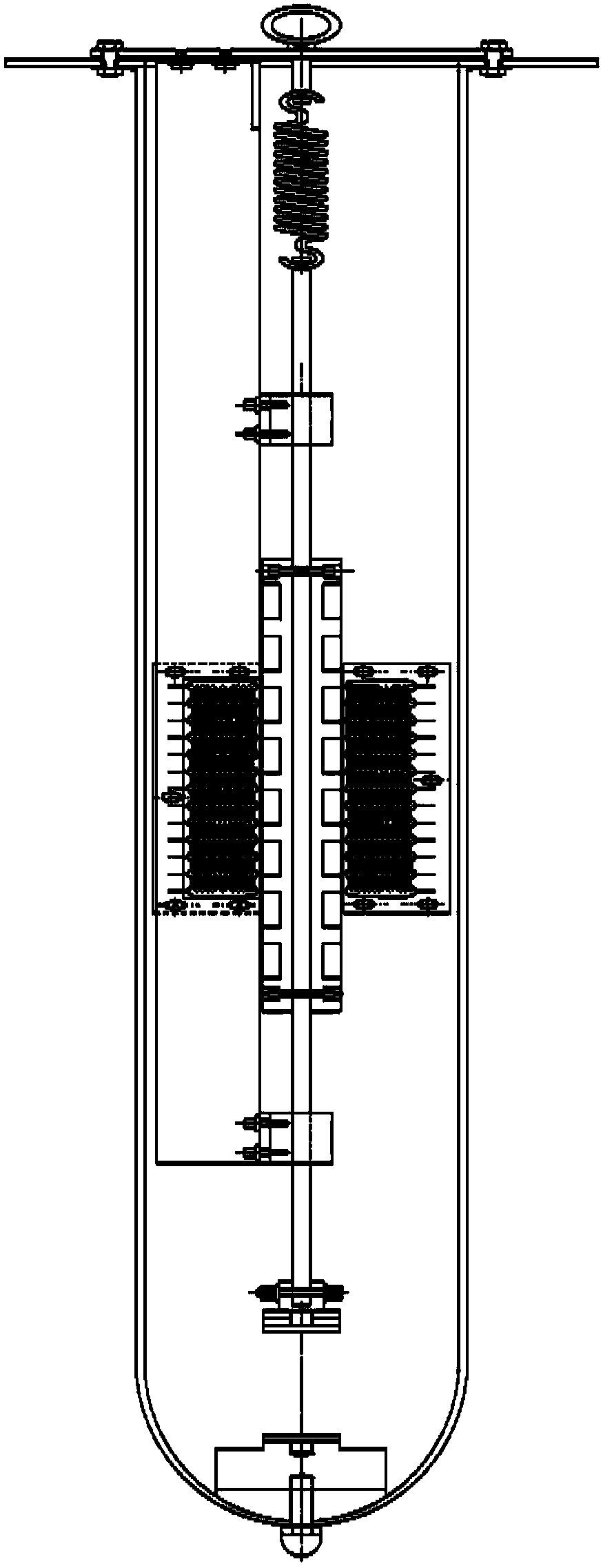
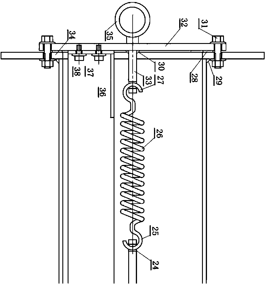
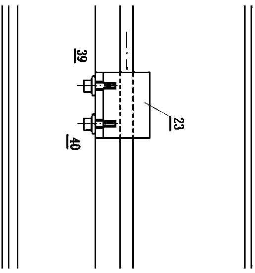
[0029] figure 1 It is a structural diagram of the whole part of a floating tube wave generator provided by an embodiment of the present invention, figure 2 This is a structural diagram of the first part of a floating tube wave generator provided by an embodiment of the present invention, image 3 This is a structural diagram of the second part of the floating tube wave generator provided by an embodiment of the present invention, Figure 4 This is a structural diagram of the third part of the floating tube wave generator provided by an embodiment of the present invention, Figure 5 This is a structural diagram of the fourth part of a floating tube wave generator provided by...


PUM


Abstract

The invention discloses a float tube type wave-activated generator, which comprises a sealed metal tube, as well as a rotor system, a stator system, a hanger spring and a slide rail all arranged in the sealed metal tube, wherein the stator system is arranged on an inner tube wall of the sealed metal tube; the rotor system is arranged on the slide rail positioned in a cavity formed by the stator system in an enclosing manner; the upper end of the slide rail is hung at the hanger spring arranged at the lower end of a sealing cover plate; the whole slide rail-rotor system is hung at the middle of the stator system; a slide rail balance weight arranged at the lower end of the slide rail enables the hanger spring to realize most active elasticity, and the slide rail-rotor system is enabled to reciprocate up and down in case of any slight wave fluctuation. According to the wave-activated generator disclosed by the invention, a linear electric generator, the hanger spring, the slide rail, a protection magnet and the balance weight are arranged in the sealed metal tube; through arrangement of the balance weight for a float tube, the float tube can always keep the upright state and suspends at a fluctuation layer with most active wave fluctuation; when multiple float tube type wave-activated generators are mounted in parallel, rigid supports are used for mutual supporting, so that distances between the wave-activated generators can be kept, collision can be avoided and large-scaled electricity generation can be formed.

Description

Technical field [0001] The invention relates to a hydroelectric generator, in particular to a device that uses wave energy to generate electricity. Background technique [0002] The ocean is vast, accounting for 70.8% of the earth's surface. The waves are endless and never stop. The ocean is "three-foot waves without wind", and the waves contain huge energy. Using ocean waves to generate electricity is of great significance to solving the world's energy problems. Therefore, countries all over the world have been constantly seeking a variety of safe, environmentally friendly, convenient and applicable, inexpensive and good-quality renewable energy sources and have been effectively utilized. Rivers, rivers, lakes, and seas contain huge wave power resources [0003] However, the existing wave energy generators have the following shortcomings: unreasonable structure, no attention to setting the wave passing speed and emergency stop shape, insufficient use of wave wave amplitude and v...

Claims


Application Information

Patent Timeline
Patent Type & Authority Applications(China)
IPC IPC(8): F03B13/14F03B11/00
CPCY02E10/226Y02E10/38Y02E10/20Y02E10/30
Inventor 沈家同
Owner CHONGQING TONGLI INDAL
Learn More