Gas spring device

A technology of gas springs and spring rods, applied in the field of elastic devices

Inactive Publication Date: 2013-11-20
林建斌
View PDF7 Cites 4 Cited by
  • Summary
  • Abstract
  • Description
  • Claims
  • Application Information

AI Technical Summary

Problems solved by technology

[0005] The present invention aims at the problem of complex design of the original gas spring structure and high manufacturing and maintenance costs, and proposes a gas spring device with a simple and unique structural design. Easy to use, low cost, and can achieve the functional effect that the existing gas spring device should have

Method used


Image

  • Gas spring device

Examples


Embodiment Construction

[0015] The present invention will be further described below in conjunction with accompanying drawing.

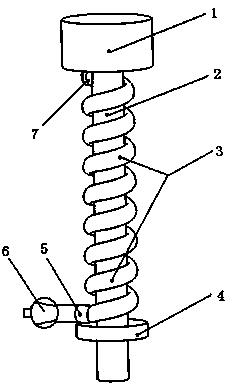
[0016] Such as figure 1 As shown, a gas spring device is mainly composed of a load-bearing device 1, a spring rod 2, a spiral gas spring 3, a gasket 4, a valve core 5, an air compressor 6, and a sealing valve 7.

[0017] Such as figure 1 As shown, the helical gas spring 3 is a helical high-pressure rubber tube made of rubber material, and the helical gas spring 3 is coiled on the spring rod 2 .

[0018] Such as figure 1 As shown, a sealing valve 7 is installed on the top of the helical gas spring 3, and a valve core 5 is installed on the end of the helical gas spring 3.

[0019] Such as figure 1 As shown, the air compressor 6 is connected with the valve core 7, and through the valve core 7, the air compressor 6 rushes into the spiral gas spring 3 with high-pressure air.

[0020] Such as figure 1 As shown, the load-bearing device 1 and the spring 2 rod are an inte...


PUM


Abstract

The invention discloses a gas spring device. The gas spring device is mainly composed of a load bearing device, a spring rod, a spiral gas spring, a gasket, a valve core, an air compressor and a seal valve. The spiral gas spring is a spiral high-pressure rubber pipe made of rubber material, and the spiral gas spring circles around the spring rod; the seal valve is arranged at the top end of the spiral gas spring, and the valve core is arranged at the tail end of the spiral gas spring; the air compressor is connected with the valve core, and through the valve core, high-pressure air is ejected into the spiral gas spring by the air compressor. According to the gas spring device, due to the fact that the high-pressure air is ejected into the spiral gas spring, the function of an original gas spring is achieved, and the good effect is achieved. The gas spring device is simple and special in structural design, simple in using and operating method, low in manufacturing and processing cost, and easy to maintain, and has relatively wide market prospect and promotion value.

Description

technical field [0001] The invention relates to an elastic device formed by an air compression system, in particular to an air spring device. Background technique [0002] The gas spring device has a good buffering and vibration reduction effect, and the gas spring is small in size and low in cost, and is widely used in various fields. The working principle of the gas spring is to fill the airtight pressure cylinder with an inert gas or an oil-gas mixture to make the cavity [0003] The pressure is several times or dozens of times higher than the atmospheric pressure, and the cross-sectional area of ​​the piston rod is smaller than the cross-sectional area of ​​the piston to produce [0004] The generated pressure difference is used to realize the movement of the piston rod. Chinese Patent No. CN2687418Y discloses a gas spring, which is mainly composed of a cylinder liner, a piston, a piston rod, a guide sleeve, and a tail seal. A packing groove is processed near one end o...

Claims


Application Information

Patent Timeline
Patent Type & Authority Applications(China)
IPC IPC(8): F16F9/02
Inventor 林建斌
Owner 林建斌
Why Eureka
Try Eureka