
Method for shaping gauss beam into flat-topped beam

A flat-top beam and Gaussian beam technology, applied in the field of non-imaging optics, can solve the problems of great influence on the results and long calculation time of the global algorithm, and achieve the effect that is beneficial to processing

Active Publication Date: 2013-11-20
HARBIN INST OF TECH
View PDF5 Cites 15 Cited by
  • Summary
  • Abstract
  • Description
  • Claims
  • Application Information

AI Technical Summary

Problems solved by technology

[0005] The present invention is to solve the problem that the calculation time of the global algorithm is long, and the setting of the initial phase of the local algorithm has a great influence on the result, and provides a method for realizing Gaussian beam shaping into a flat-hat beam

Method used


Image

  • Method for shaping gauss beam into flat-topped beam
  • Method for shaping gauss beam into flat-topped beam
  • Method for shaping gauss beam into flat-topped beam

Examples


specific Embodiment approach 1

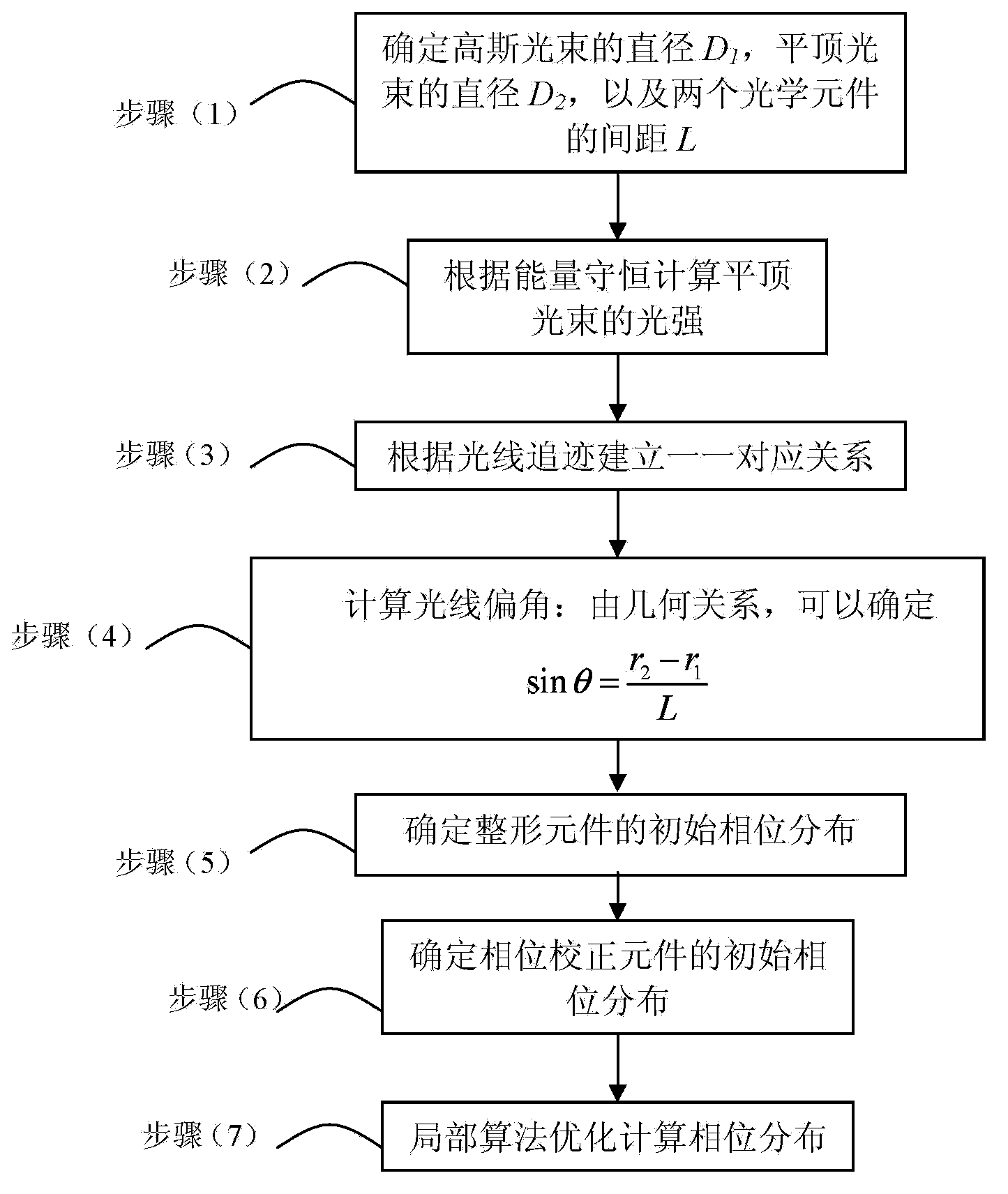
[0025] Specific implementation mode one: combine Figure 1 ~ Figure 4 Describe this embodiment, a method for realizing Gaussian beam shaping into a flat-hat beam in this embodiment is implemented in the following steps:

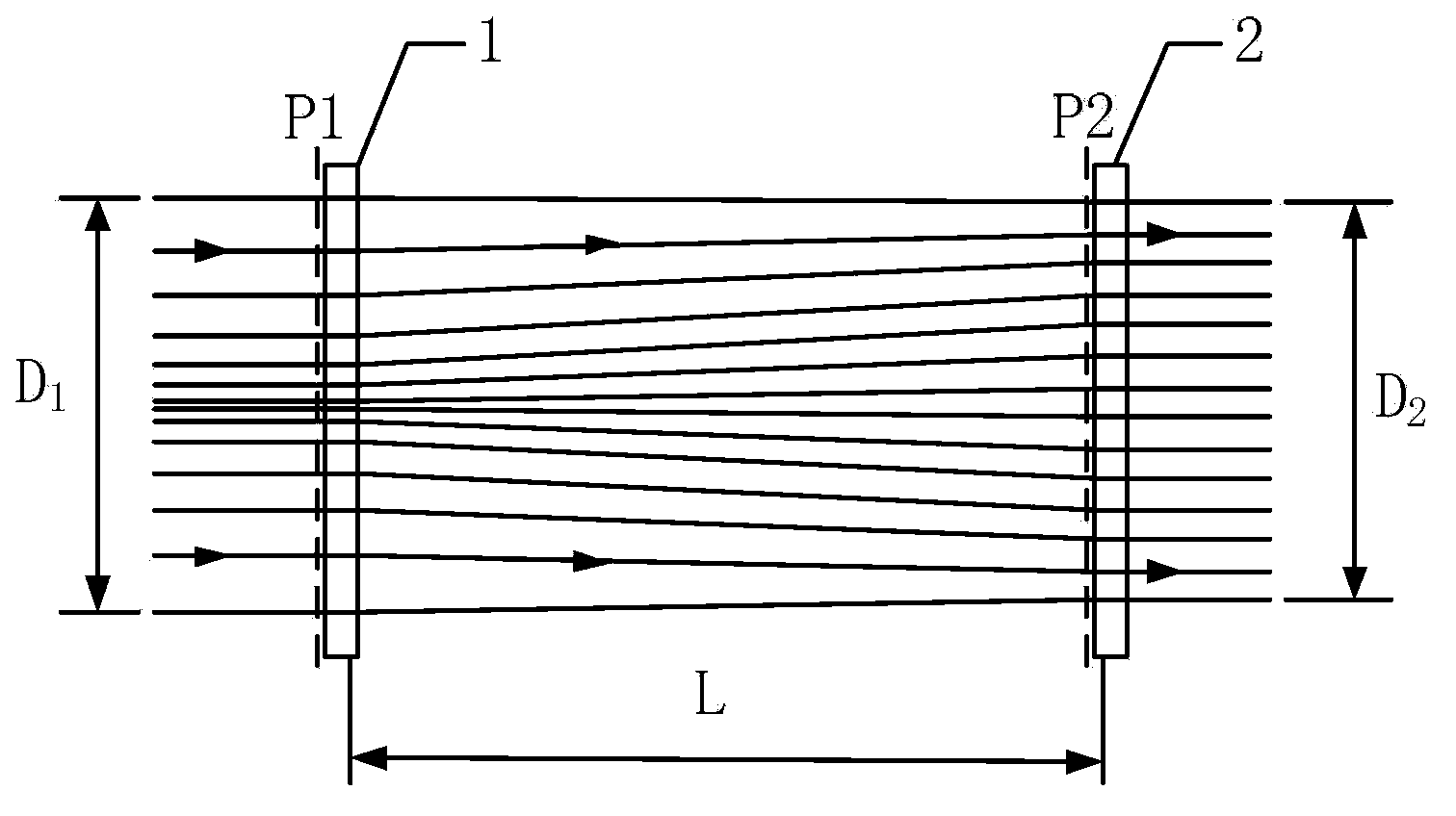
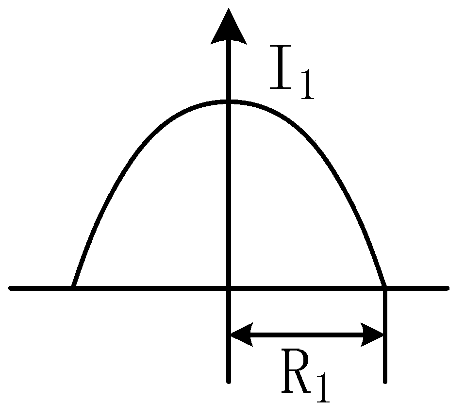
[0026] (1) According to figure 2 Determine the diameter D of the Gaussian beam 1 , the diameter of the top-hat beam D 2 , and the distance L between the two optical elements: as image 3 , if the radius of the laser Gaussian beam is R 1 , then D 1 =2R 1 ;Such as Figure 4 , if the required top-hat beam radius is R 2 , then D 2 =2R 2 ; In order to ensure that the deflection angle of the light after passing through the optical shaping element is as small as possible, generally L≥D 1 ;

[0027] (2) Calculate the light intensity of the top-hat beam according to energy conservation;

[0028] (3) Establish a one-to-one correspondence based on ray tracing;

[0029] (4) Calculate the light deflection angle: from the geometric relationship, it can be det...

specific Embodiment approach 2

[0038] Specific embodiment two: the difference between this embodiment and specific embodiment one is: in step (2): the light intensity I of the top-hat beam 2 can be determined by

[0039] ∫ 0 R 1 I 1 exp ( - r 1 ω 1 ) 2 · 2 π r 1 · dr 1 = ∫ 0 R 2 I 2 · 2 π r 2 · dr 2

[0040] In the formula, I 1 is the central li...

specific Embodiment approach 3

[0042] Specific implementation mode 3: The difference between this implementation mode and specific implementation mode 1 or 2 is that in step (3), the one-to-one correspondence relationship is established according to ray tracing, specifically:

[0043] The distance r from the beam center on the P1 plane 1 The light emitted at the place is incident on the P2 surface and the distance from the center of the beam is r 2 , where 0≤r 1 ≤D 1 ,D 1 ≤r 2 ≤D 2 , and satisfy the relation

[0044] ∫ 0 r 1 I 1 exp ( - r 1 ω 1 ) 2 · 2 π r · dr = ∫ 0 ...


PUM


Abstract

The invention relates to the field of non-image optics, in particular to a method for shaping a gauss beam into a flat-topped beam, aims to solve the problems that the global algorithm takes much time and the initial phase setting of the local algorithm has great impact on a result, and provides the method for shaping the gauss beam into the flat-topped beam. The method comprises the following steps: (1) determining the diameter D1 of the gauss beam, the diameter D2 of the flat-topped beam and the distance L between two optical elements (including a shaping element and a phase correction element); (2) according to the energy conservation, calculating the light intensity of the flat-topped beam; (3) according to ray tracing, building an one to one correspondence relationship; (4) calculating the declination angle of a light ray; (5) determining the initial phase distribution of the shaping element; (6) determining the initial phase distribution of the phase correction element; (7) conducting optimizing calculation on the phase distribution according to the local algorithm. The method is applicable to the field of non-imaging optics.

Description

technical field [0001] The invention relates to the field of non-imaging optics, in particular to a method for shaping a Gaussian beam into a flat-hat beam. Background technique [0002] Since the advent of laser, it has been widely used. In some application fields, there are high requirements for the uniformity of the laser beam, such as in laser lithography, laser processing, laser storage and recording, medical fields, etc., so it is necessary to shape the Gaussian beam into a uniform distribution through a special design method. Flat top beam. [0003] There are many beam shaping methods, using binary optical elements, aspheric lens groups, holographic filters, amplitude modulation gratings, liquid crystal spatial light modulators, microlens array shaping, birefringent lens groups, and phase beam shaping can be Gaussian The beam is shaped into a top-hat beam. [0004] In comparison, the structure of the aspheric lens group method is simple, but the diffraction effect ...

Claims


Application Information

Patent Timeline
Patent Type & Authority Applications(China)
IPC IPC(8): G02B27/09
Inventor 胥全春俞建杰刘永凯周彦平于思源杜继东谢小龙高鹏涛马晶谭立英
Owner HARBIN INST OF TECH
Learn More