Method for shaping gauss beam into flat-topped beam
A flat-top beam and Gaussian beam technology, applied in the field of non-imaging optics, can solve the problems of great influence on the results and long calculation time of the global algorithm, and achieve the effect that is beneficial to processing
- Summary
- Abstract
- Description
- Claims
- Application Information
AI Technical Summary
Problems solved by technology
Method used
Image
Examples
specific Embodiment approach 1
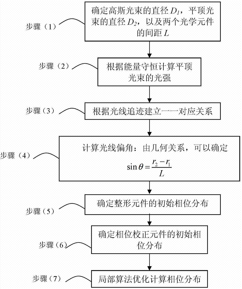
[0025] Specific implementation mode one: combine Figure 1 ~ Figure 4 Describe this embodiment, a method for realizing Gaussian beam shaping into a flat-hat beam in this embodiment is implemented in the following steps:
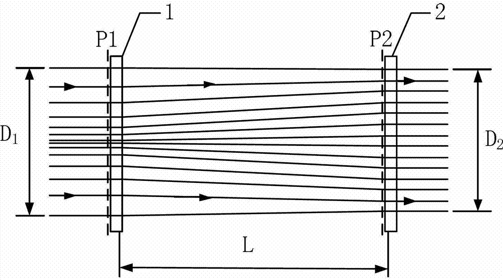
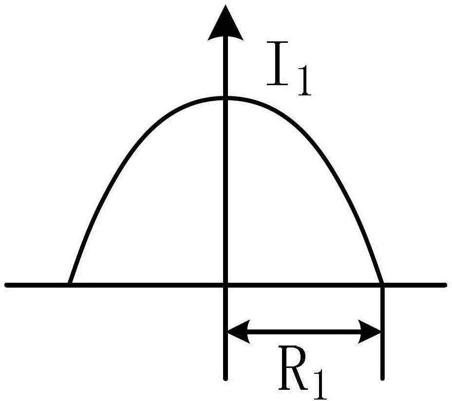
[0026] (1) According to figure 2 Determine the diameter D of the Gaussian beam 1 , the diameter of the top-hat beam D 2 , and the distance L between the two optical elements: as image 3 , if the radius of the laser Gaussian beam is R 1 , then D 1 =2R 1 ;like Figure 4 , if the required top-hat beam radius is R 2 , then D 2 =2R 2 ; In order to ensure that the deflection angle of the light after passing through the optical shaping element is as small as possible, generally L≥D 1 ;
[0027] (2) Calculate the light intensity of the top-hat beam according to energy conservation;
[0028] (3) Establish a one-to-one correspondence based on ray tracing;
[0029] (4) Calculate the light deflection angle: from the geometric relationship, it can be determ...
specific Embodiment approach 2
[0038] Specific embodiment two: the difference between this embodiment and specific embodiment one is: in step (2): the light intensity I of the top-hat beam 2 can be determined by
[0039] ∫ 0 R 1 I 1 exp ( - r 1 ω 1 ) 2 · 2 π r 1 · dr 1 = ∫ 0 R 2 I 2 · 2 π r 2 · dr 2
[0040] In the formula, I 1 is the central li...
specific Embodiment approach 3
[0042] Specific implementation mode 3: The difference between this implementation mode and specific implementation mode 1 or 2 is that in step (3), the one-to-one correspondence relationship is established according to ray tracing, specifically:
[0043] The distance r from the beam center on the P1 plane 1 The light emitted at the place is incident on the P2 surface and the distance from the center of the beam is r 2 , where 0≤r 1 ≤D 1 ,D 1 ≤r 2 ≤D 2 , and satisfy the relation
[0044] ∫ 0 r 1 I 1 exp ( - r 1 ω 1 ) 2 · 2 π r · dr = ∫ 0 ...
PUM
 Abstract
Description
Claims
Application Information
 - R&D
- Intellectual Property
- Life Sciences
- Materials
- Tech Scout
- Unparalleled Data Quality
- Higher Quality Content
- 60% Fewer Hallucinations
Browse by: Latest US Patents, China's latest patents, Technical Efficacy Thesaurus, Application Domain, Technology Topic, Popular Technical Reports.
© 2025 PatSnap. All rights reserved.Legal|Privacy policy|Modern Slavery Act Transparency Statement|Sitemap|About US| Contact US: help@patsnap.com


