High-precision resistance-free band-gap reference voltage source

A reference voltage source, no resistance technology, applied in the direction of adjusting electrical variables, control/regulation systems, instruments, etc., can solve the problems of unsatisfactory temperature characteristics, inability to provide resistance models, increase the application limitations of bandgap references, etc., to achieve good Temperature characteristics, effects of high reference voltage accuracy

Inactive Publication Date: 2013-11-20
UNIV OF ELECTRONICS SCI & TECH OF CHINA
View PDF5 Cites 16 Cited by
  • Summary
  • Abstract
  • Description
  • Claims
  • Application Information

AI Technical Summary

Problems solved by technology

It is a high-order item, so the temperature characteristic of VBE is nonlinear, so that the negative temperature coefficient of VBE at low temperature is relatively small, and the negative temperature coefficient of VBE at high temperature is relatively large. The traditional bandgap reference only performs first-order compensation for it. Obtain the reference voltage V REF The temperature characteristic curve such as figure 2 As shown in, it can be seen that the reference voltage V REF The temperature characteristics are not ideal
At the same time, traditional bandgap reference circuits mostly contain resistors, and many processes cannot provide resistance models, which increases the limitations of traditional bandgap reference applications

Method used


Image

  • High-precision resistance-free band-gap reference voltage source
  • High-precision resistance-free band-gap reference voltage source
  • High-precision resistance-free band-gap reference voltage source

Examples


Embodiment Construction

[0027] specific implementation plan

[0028] The present invention will be further elaborated below in conjunction with the accompanying drawings and specific embodiments.

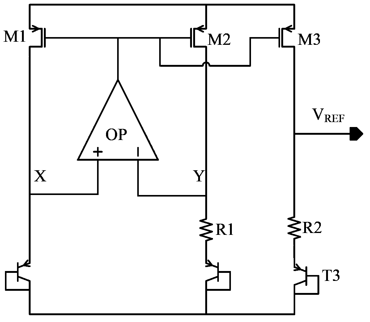
[0029] The high-precision non-resistance bandgap reference voltage source of the present invention includes a negative temperature current generation circuit, a positive temperature current generation circuit, a first-order positive temperature voltage superposition circuit, a low temperature current compensation circuit, and a high temperature current compensation circuit. The negative temperature current generating circuit is used to generate a negative temperature current, and the positive temperature current generating circuit is used to generate a positive temperature current. A base of the positive temperature current generating circuit and an emitter of a PNP transistor Q1 whose collector is grounded are connected to A first-order positive temperature voltage superposition circuit, the positive temp...


PUM


Abstract

The invention relates to a high-precision resistance-free band-gap voltage reference source. The high-precision resistance-free band-gap voltage reference source comprises a minus-temperature current generating circuit, a right-temperature current generating circuit, a first-order right-temperature voltage overlaying circuit, a low-temperature current compensating circuit and a high-temperature current compensating circuit. The minus-temperature current generating circuit is used for generating minus-temperature currents. The right-temperature current generating circuit is used for generating right-temperature currents. One base electrode of the right-temperature current generating circuit and an emitting electrode of a PNP audion Q1 with a collector electrode grounded are connected to the first-order right-temperature voltage overlaying circuit, right-temperature currents supply bias currents to the first-order right-temperature voltage overlaying circuit, the first-order right-temperature voltage overlaying circuit achieves overlaying between right-temperature voltage and minus-temperature voltage and outputs a VREF. The high-precision resistance-free band-gap reference voltage source has the very good temperature features, and can provide higher voltage reference precision. A resistor model is not adopted in the high-precision resistance-free band-gap voltage reference source, and the high-precision resistance-free band-gap voltage reference source can be compatible with certain low-precision technologies without resistors or resistor modules.

Description

technical field [0001] The invention relates to a high-precision non-resistance bandgap reference circuit, which belongs to the technical field of analog integrated circuits. Background technique [0002] The reference voltage source is a very important basic circuit unit in the field of integrated circuit electronics technology. It is widely used in analog and digital converters, power converters, power amplifiers and other circuits to provide the system with a voltage reference that does not vary with temperature and supply voltage. [0003] Traditional bandgap voltage references such as figure 1 As shown, the clamping position of the operational amplifier OP ensures that the voltages of the two points X and Y are equal, and the current mirror formed by the PMOS transistors M1, M2 and M3 makes the two currents equal. The reference output voltage is obtained according to the voltage-current characteristics of the bipolar transistor: [0004] V ...

Claims


Application Information

Patent Timeline
Patent Type & Authority Applications(China)
IPC IPC(8): G05F1/567
Inventor 周泽坤许天辉苟超朱世鸿张其营张庆岭张波
Owner UNIV OF ELECTRONICS SCI & TECH OF CHINA
Why Eureka
Try Eureka