Space manipulator modeling method based on differential geometry

A technology of space manipulators and modeling methods, applied in special data processing applications, instruments, electrical digital data processing, etc., can solve problems such as lack of research results and methods

Active Publication Date: 2013-11-20
HARBIN INST OF TECH
View PDF3 Cites 24 Cited by
  • Summary
  • Abstract
  • Description
  • Claims
  • Application Information

AI Technical Summary

Problems solved by technology

In the research process of the space manipulator, there is a requirement that the model of the space manipulator established can not only ensure the calculation efficiency and accuracy of the model, but also have a clear physical meaning. At present, there are no similar research results and methods in the literature search

Method used


Image

  • Space manipulator modeling method based on differential geometry
  • Space manipulator modeling method based on differential geometry
  • Space manipulator modeling method based on differential geometry

Examples


Embodiment 1

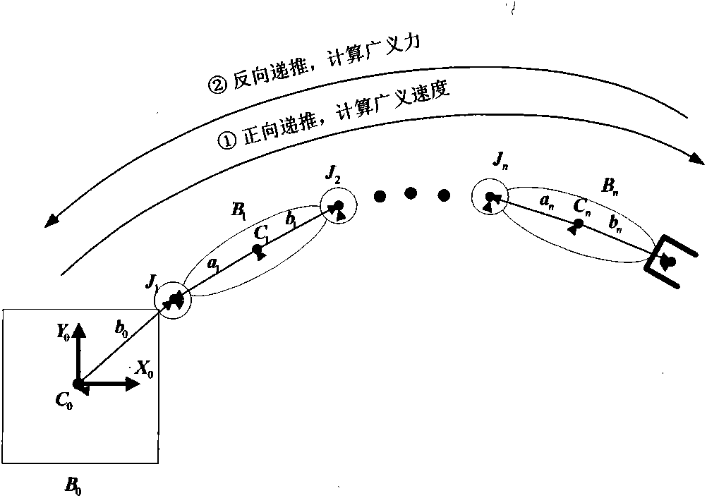
[0067] Embodiment 1, combining figure 1 , the steps of the modeling method based on differential geometry in the present invention are as follows:

[0068] Step 1: Select the zero position of the manipulator system, write out the zero position joint vector S∈se(3), the center of mass joint vector r, and the inertia matrix I.

[0069] Step 2: Calculate the positive definite symmetric matrix J related to the inertial parameters, and the coordinate position matrix M∈SE(3).

[0070] Step 3: Calculate the generalized speed of each connecting rod by forward recursion.

[0071] Step 4: Given the generalized force F acting on the end effector n+1 , calculate the generalized force of each connecting rod by reverse recursion.

[0072] Step 5: Write each quantity as a matrix expression to obtain a compact kinetic equation.

Embodiment 2

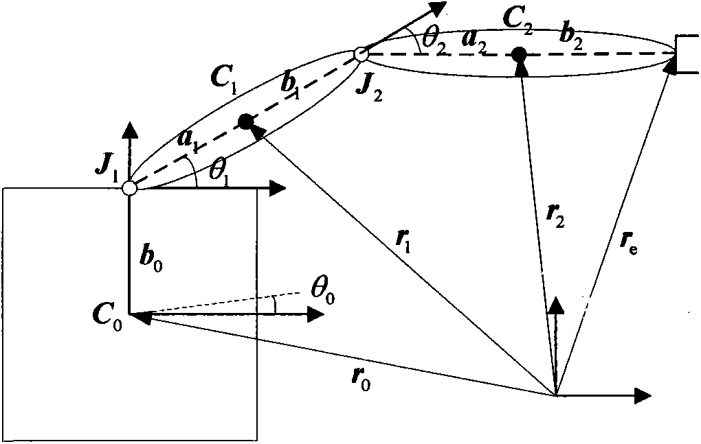
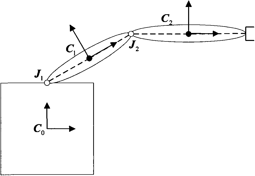
[0073] Example 2, combined with figure 1 , figure 2 , the zero position of the manipulator system studied in the present invention is selected in this way, the center of mass of the base and the joints of the connecting rods are selected as the origin of the fixed coordinate system of the base and the connecting rods at all levels respectively, and the coordinate system of the base is recorded as 0 No., the connecting rods at all levels are marked as i (i=1,...,n), the fixed coordinate system of the end effector is marked as (n+1), and the origin is selected at the end of the connecting rod. According to the conventions of robotics, the joint variables of each link are specified as

[0074]

[0075] with q i =0 is the zero bit.

[0076] For the planar 2R free-flying space manipulator system, the zero joint vector S i =[0 0 1 0 0 0 ] T ; centroid position vector r 0 =[0 0 0] T , r 1 =[a 1 0 0] T , r 2 =[a 2 0 0] T , where a 1 、a 2 Respectively, the graphica...

Embodiment 3

[0077] Example 3, combined with figure 1 , figure 2 , the matrix J defined by the present invention and the coordinate position matrix M ∈ SE (3) are calculated like this,

[0078] J i = I i - m i r ~ i 2 m i r ~ i - m i r ...


PUM


Abstract

The invention discloses a space manipulator modeling method based on different geometry. On the foundation that each level rigid body zero position of a space manipulator system is selected, initializing conditions such as a zero position joint vector, a centroid joint vector and an initial vector are calculated and given, and a matrix related to initial parameters and a coordinate position matrix are calculated. The generalized velocity of each connecting rod is calculated through forward recursion, and the generalized force of each connecting rod is calculated through reverse recursion. Each quantity is substituted into the matrixes, and a kinetic equation compact in form is written down. The model has the advantages of being uniform in modeling form and small in operating amount, improving calculation efficiency and accuracy of the space manipulator modeling, and improving the designing accuracy of the space manipulator. The space manipulator modeling method based on differential geometry can be applied to modeling of other space multi-rigid-body systems.

Description

technical field [0001] The invention belongs to the field of space manipulator model construction, and in particular relates to a space manipulator modeling method based on differential geometry. Background technique [0002] As an on-orbit maintenance device for spacecraft, the space manipulator can complete multiple tasks such as spacecraft maintenance, fuel replenishment, material transportation, and space junk cleaning, and plays an important role in space activities. [0003] In the process of program design and demonstration of space manipulator, accurate and simple mathematical model is the basis of research. However, the space manipulator works in the weightless environment of space, and there is a high degree of coupling between the floating base and the link of the manipulator. At the same time, due to the consideration of the economic cost caused when launching objects into space, the volume, mass and energy consumption of the space manipulator are greatly limite...

Claims


Application Information

Patent Timeline
Patent Type & Authority Applications(China)
IPC IPC(8): G06F17/50
Inventor 夏红伟王常虹邓雅马广程宋效正翟彦斌
Owner HARBIN INST OF TECH
Why Eureka
Try Eureka