Three-dimensional bone tissue model building method and equipment

A bone tissue and three-dimensional bone technology, applied in the field of medical electronics, can solve the problems of inability to simulate stress changes in trabecular bone, complex microstructure of cancellous bone, and poor simulation results

Inactive Publication Date: 2013-11-20
HARBIN INST OF TECH SHENZHEN GRADUATE SCHOOL
View PDF0 Cites 7 Cited by
  • Summary
  • Abstract
  • Description
  • Claims
  • Application Information

AI Technical Summary

Problems solved by technology

However, destructive mechanical experiments can not only simulate the pore structure formed by the real trabecular bone, but also cannot simulate the stress changes caused by the interaction between the trabecular bone and the bone marrow during the stress process, such as the flow of the bone marrow and the pressure on the bone marrow material. The influence of cushioning and so on on cancellous bone when it is stressed, and the destructive mechanics experiment cannot analyze the influence of the characteristics of bone marrow on cancellous bone when it is stressed
And limited by the boundary conditions, it is impossible to simulate the boundary conditions for the simulated entity system, as well as simulate the distribution of the fluid-solid coupling stress between the bone marrow and the trabecular bone, resulting in poor simulation results and an effect similar to the real results.
And, the simulated entity system cannot be recovered after being deformed by force, so repeated tests on the same entity system cannot be carried out, and because the microstructure of cancellous bone is relatively complex, it is difficult to imitate the same entity system for the same cancellous bone, and it is also impossible Ensure that the conditions for each experiment are the same, so the repeatability and verification of destructive mechanics experiments are poor, and the cost of experiments is increased

Method used


Image

  • Three-dimensional bone tissue model building method and equipment
  • Three-dimensional bone tissue model building method and equipment
  • Three-dimensional bone tissue model building method and equipment

Examples


Embodiment approach

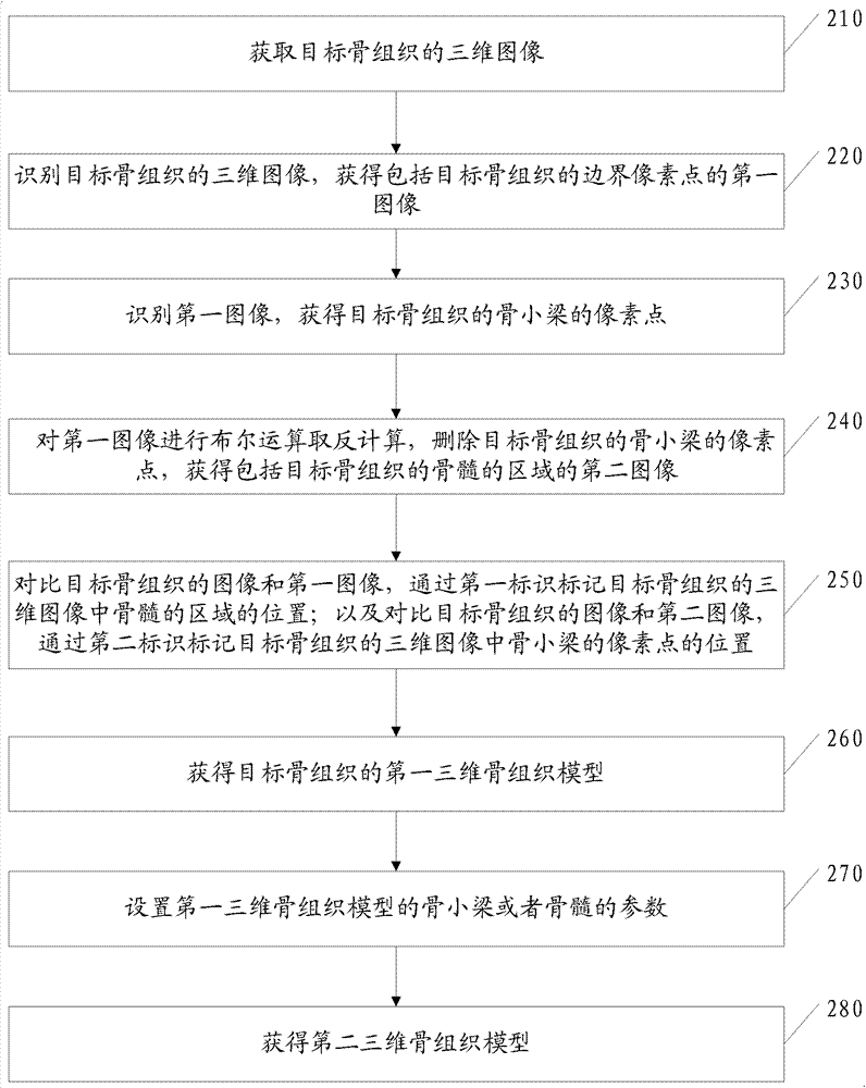
[0094] As an optional implementation, the method also includes:

[0095] A. Setting parameters of trabecular bone and / or bone marrow of the first three-dimensional bone tissue model. Wherein, setting the parameters of the trabecular bone of the first three-dimensional bone tissue model is specifically the following process:

[0096] Invoke the setting process of the porous coupling module to set the trabecular part of the target bone tissue as a linear elastic solid.

[0097] Physical parameters such as Young's modulus, Poisson's ratio, and bone density of the target bone tissue are obtained to set physical parameters such as the Young's modulus, Poisson's ratio, and bone density of the target bone tissue.

[0098] In this embodiment, setting the parameters of the bone marrow of the first three-dimensional bone tissue model is specifically setting the components of the bone marrow as fluid. Because bone marrow is composed of red bone marrow and yellow bone marrow, the propor...


PUM


Abstract

The invention discloses a three-dimensional bone tissue model building method. The method comprises the steps of obtaining the first image of a region enclosed by the boundary pixels and boundary pixels of a target bone tissue by identifying the three-dimensional image of the target bone tissue; identifying the first image; deleting the pixels of bone trabecula of the target bone tissue to obtain a second image of the marrow region of the target bone tissue, and comparing the image of the target bone tissue and the first image; identifying the position of the marrow region of the target bone tissue in the three-dimensional image of the target bone tissue by a first identifier; comparing the image of the target bone tissue and the second image; identifying the positions of the pixels of the bone trabecula of the target bone tissue in the three-dimensional image of the bone tissue by the second identifier so as to obtain a first three-dimensional bone tissue model of the target bone tissue, thereby obtaining the forms of the real bone trabecula and the marrow, and obtaining the three-dimensional bone tissue model which realistically displays the inner form of the target bone tissue.

Description

technical field [0001] The invention relates to the technical field of medical electronics, and specifically designs a method and equipment for building a three-dimensional bone tissue model. Background technique [0002] Cancellous bone includes trabecular bone and bone marrow. Bone marrow is an important component of cancellous bone. The filling of pores formed by trabecular bone is bone marrow. The existing three-dimensional bone tissue finite element model can display the distribution of the real shape of cancellous bone and provide information on the spatial distribution of cancellous bone. However, the existing three-dimensional bone tissue finite element model can only show the shape of cancellous bone and roughly show the pore structure of bone trabecula. Under the microscopic display, the size and shape of each pore in the pore structure obtained by modeling is The same or regular distribution has a large error with the real pore structure, so the real pore structu...

Claims


Application Information

Patent Timeline
Patent Type & Authority Applications(China)
IPC IPC(8): G06T17/00
Inventor 马婷朱俊
Owner HARBIN INST OF TECH SHENZHEN GRADUATE SCHOOL
Why Eureka
Try Eureka