
Cabling pay-off machine with lifting structure

A lifting structure and pay-off machine technology, applied in the direction of cable/conductor manufacturing, electrical components, circuits, etc., can solve the problems of cable damage, time-consuming and labor-intensive operation, and unusable cables, so as to improve work efficiency and transmission stability Good, guarantee the effect of processing quality

Active Publication Date: 2015-07-22
ZHEJIANG SHIP ELECTRONICS TECH
View PDF5 Cites 0 Cited by
  • Summary
  • Abstract
  • Description
  • Claims
  • Application Information

AI Technical Summary

Problems solved by technology

[0002] Power cables and communication cables are the second pillar products of China's export products. A large cable is twisted by multiple or pairs of small cables at a certain helical distance to improve the bending resistance of the cable and improve the electronic performance. The anti-interference ability of the signal, so that the machine used for cable forming is applied. For example, when four two-strand cables need to be twisted, the cable forming device needs to cooperate with the wire pay-off device and the wire take-up device to complete the twisting of the cables. , the biggest shortcoming of the existing cable forming machine is that there is no additional lifting mechanism for the pay-off reel, because the pay-off reel is in a parallel plane with the pay-off reel during normal pay-off, so when a new pay-off reel needs to be replaced It is cumbersome to operate the wire reel, and the pay-off reel needs to be taken out from its upper part, which is time-consuming and labor-intensive to operate. In addition, due to the unreasonable internal structure setting of the wire pay-off device or the wire take-up device during twisting, the work efficiency is relatively low, and Because the pay-off device is passive to pay out the wire, it is easy to cause the cable to break, and at the same time, the tension is not stable during the cable-forming process, and the stability is poor, and it is easy to cause damage to the cable during the cable-forming process. can not be used

Method used


Image

  • Cabling pay-off machine with lifting structure
  • Cabling pay-off machine with lifting structure
  • Cabling pay-off machine with lifting structure

Examples


Embodiment Construction

[0023] The following are specific embodiments of the present invention in conjunction with the accompanying drawings to further describe the technical solutions of the present invention, but the present invention is not limited to these embodiments.

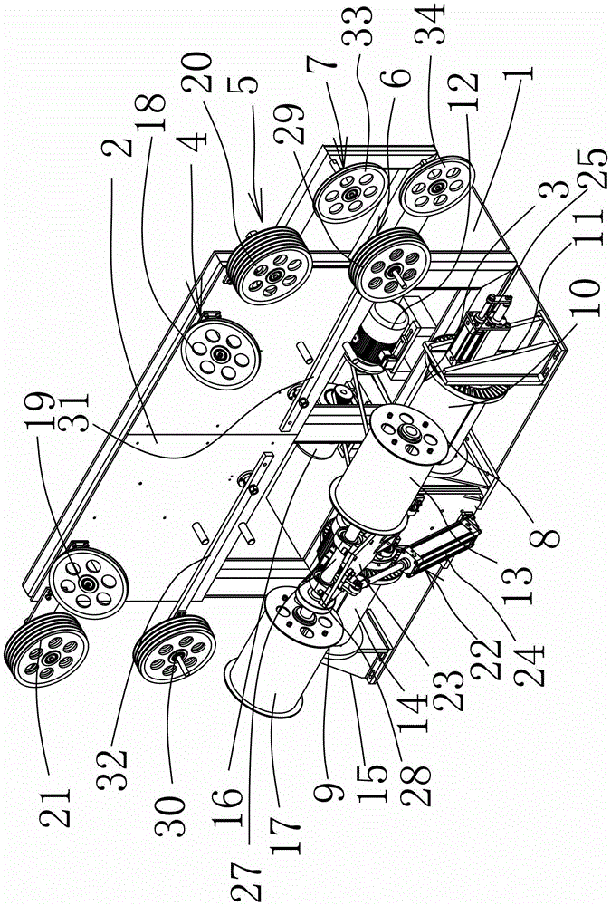
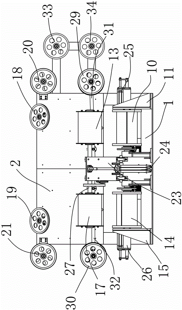
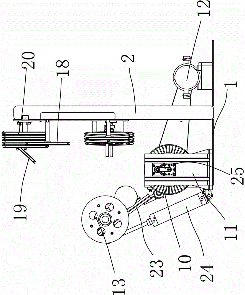
[0024] In the figure, the frame 1; the fixed plate 2; the pay-off mechanism 3; the pay-off guide mechanism 4; the pay-off transition mechanism 5; the tension control mechanism 6; the outlet mechanism 7; the right pay-off mechanism 8; the left pay-off mechanism 9; One pay-off reel 10; first pay-off support 11; first pay-off drive motor 12; first pay-off reel wheel 13; second pay-off reel 14; second pay-off support 15; second pay-off drive motor 16 ; The second pay-off reel 17; the first tangential reel 18; the second tangential reel 19; the first transition reel 20; the second transition reel 21; the pay-off reel lifting mechanism 22; lift The fixed platform 23; lift the driving cylinder 24; the first installation driving cylinder 25...


PUM


Abstract

The invention belongs to the field of mechanical technique and provides a cabling pay-off machine with a lifting structure. The cabling pay-off machine with the lifting structure comprises a machine frame and a fixed plate arranged on the rack, wherein a pay-off mechanism and a pay-off plate wheel uplifting mechanism are arranged on the machine frame; a pay-off guiding mechanism, a pay-off transition mechanism, a tension control mechanism and an outgoing wire mechanism are arranged on the fixed plate; the pay-off plate wheel uplifting mechanism comprises an uplifting fixed station and an uplifting drive cylinder, the lower end of the uplifting drive cylinder is hinged on the machine frame, the pay-off mechanism is arranged on the uplifting fixed station, and the fixed station is upwards uplifted under the effect of the uplifting drive cylinder around a hinge joint. The cabling pay-off machine with the lifting structure has the advantages that the pay-off plate wheel uplifting mechanism is additionally adopted, as the pay-off plate wheel and a pay-off plate are in the parallel horizontal plane in normal pay-off process, the uplifting fixed station can be automatically adjusted to be in the upper and lower horizontal planes with intervals through the uplifting drive cylinder, so that the pay-off plate wheel after pay-off can be freely and conveniently replaced by a new pay-off plate wheel, the operation is convenient and rapid, and the working efficiency is improved.

Description

Technical field [0001] The invention belongs to the technical field of machinery, and relates to a device for processing cables or cables, and in particular to a cable pay-off machine with a lifting structure. Background technique [0002] Power cables and communication cables are the second pillar products of our country’s export products. A large cable is made up of multiple or multiple pairs of small cables twisted at a certain helix distance to improve the cable’s bending resistance and electronics. The anti-interference ability of the signal, so that the machine used to form the cable will be applied. For example, when four two-strand cables need to be twisted, the cable needs to cooperate with the pay-off device and the take-up device to complete the twisting of the cable. The biggest disadvantage of the existing cable forming machine is that there is no additional lifting mechanism for the pay-off reel. Because the pay-off reel is in a parallel plane with the pay-off reel ...

Claims


Application Information

Patent Timeline
Patent Type & Authority Patents(China)
IPC IPC(8): H01B13/02H01B13/00
Inventor 竺永宏李鹏王国强王廼宁柳聪孙明星
Owner ZHEJIANG SHIP ELECTRONICS TECH
Learn More