
A permanent magnet motor

A permanent magnet motor and permanent magnet technology, applied in the direction of electric components, magnetic circuit rotating parts, electrical components, etc., can solve the problems of limited use range of permanent magnet motors, low efficiency of working conditions, waste of magnetic field, etc., and achieve material saving rate , prolong the service life and improve the permanent magnet utilization

Active Publication Date: 2016-02-24
QIANNAN HONGLIAN COMM
View PDF8 Cites 0 Cited by
  • Summary
  • Abstract
  • Description
  • Claims
  • Application Information

AI Technical Summary

Problems solved by technology

However, the existing permanent magnet motors mainly have the following disadvantages: (1) Since the permanent magnet is a single layer, there is only one working surface for the permanent magnet and the electromagnet, and the working efficiency is low; (2) Since the motor rotor is a whole, the limitation (3) The magnetic field generated by the winding wire of the existing permanent magnet motor rotor passing through the diameter part of the rotor from the starting end to the ending end is wasted, even if With segmental winding, only one pole can be used for the N pole and S machine of the electromagnetic after power-on, which consumes a lot of power and has low efficiency.

Method used


Image

  • A permanent magnet motor
  • A permanent magnet motor
  • A permanent magnet motor

Examples


Embodiment Construction

[0021] The technical solution of the present invention will be further described below in conjunction with the accompanying drawings, but the scope of protection is not limited to the description.

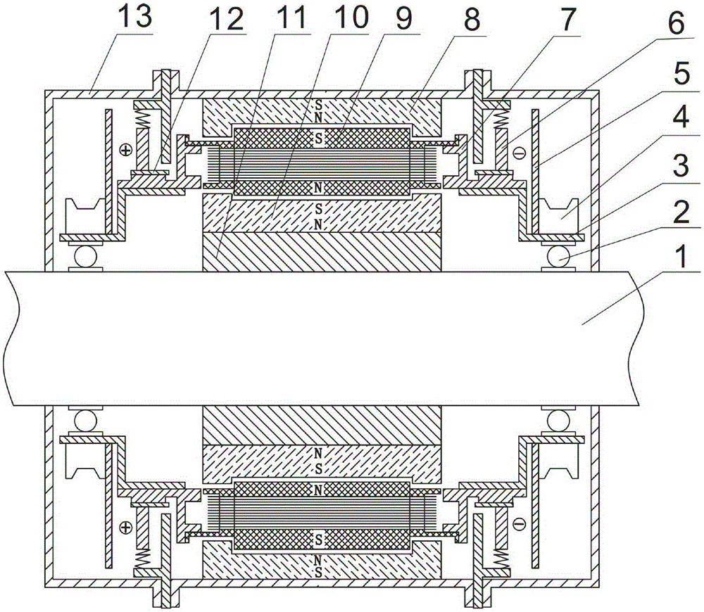
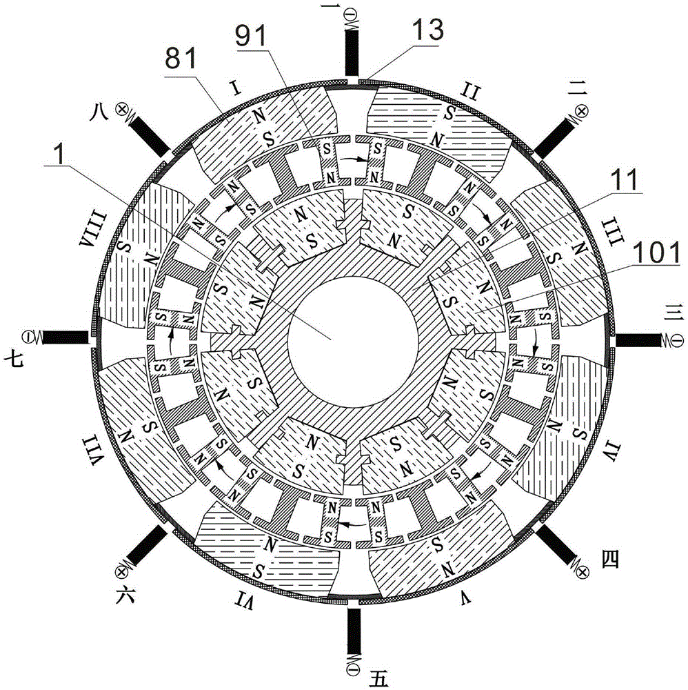
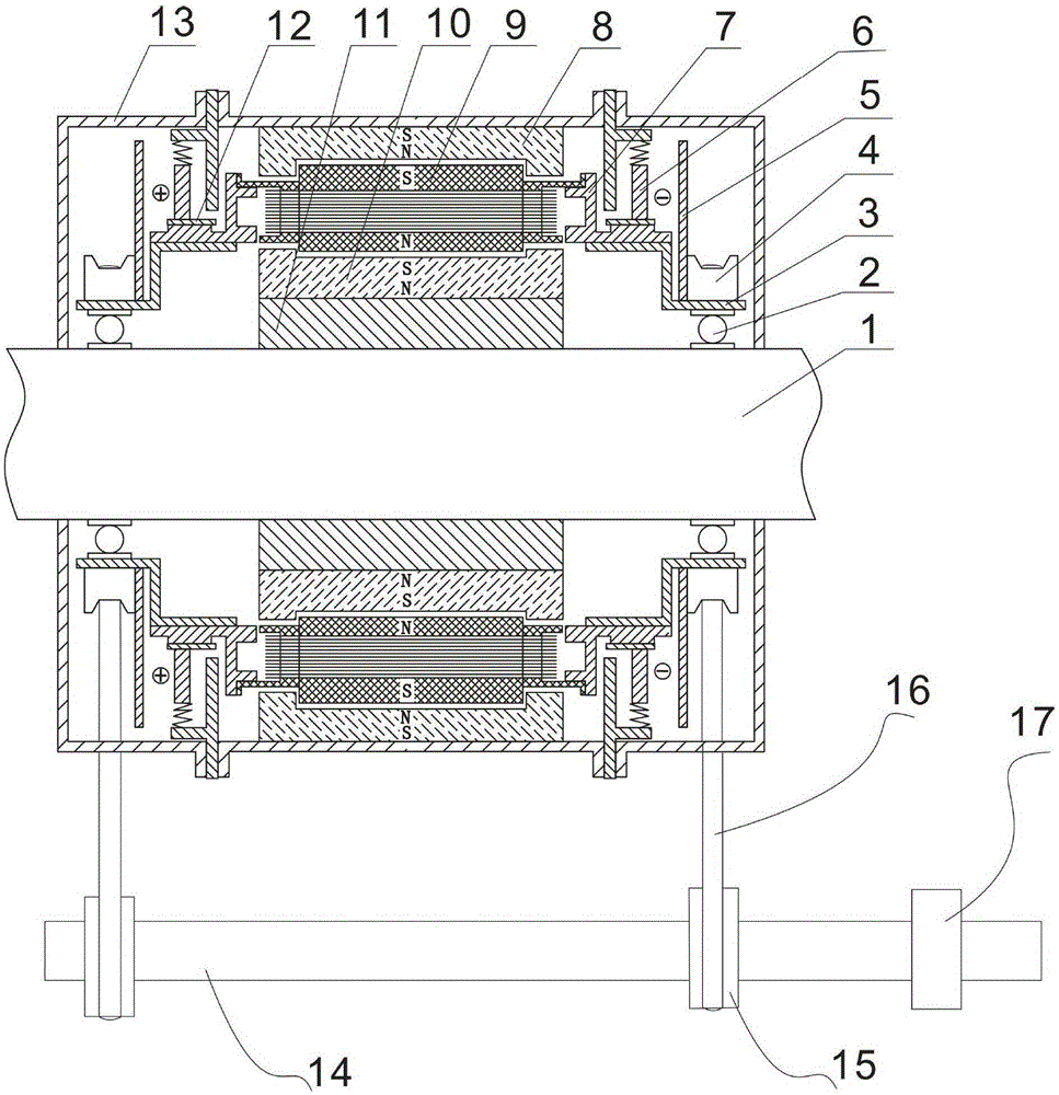
[0022] Such as figure 1 , figure 2 As shown, a permanent magnet motor according to the present invention includes a casing 13 and a motor shaft 1 placed in the casing 13, an inner permanent magnet 10 and an outer permanent magnet 8, and the two ends of the motor shaft 1 are respectively fixed on the casing 13, the inner permanent magnet 10 is installed on the motor shaft 1 through the inner permanent magnet combination bracket 11, the outer permanent magnet 8 is installed on the shell 13, and an electromagnet 9 is arranged between the outer permanent magnet 8 and the inner permanent magnet 10. The motor shaft 1 is located on both sides of the inner permanent magnet combination bracket 11, and the bearings 2 are respectively symmetrically installed through the bearing fixing brack...


PUM


Abstract

The invention discloses a permanent magnet motor, which comprises a shell, a motor shaft, an inner permanent magnet and an outer permanent magnet, wherein the motor shaft, the inner permanent magnet and the outer permanent magnet are arranged in the shell, two ends of the motor shaft are symmetrically provided with bearings respectively through bearing fixing supports, the inner permanent magnet is installed on the motor shaft through an inner permanent magnet combination support, the outer permanent magnet and the inner permanent magnet are provided with an electromagnet therebetween, and the electromagnet is connected with the bearing fixing supports through the electromagnet combination support. The permanent magnet motor increases the magnetic field greatly and improves the permanent magnet utilization rate through arranging the outer permanent magnet and the inner layer permanent magnet. As an independent coil design is adopted by electromagnetic coils, an N pole and an S pole generated when the electromagnetic coils are electrified can both generate a pushing force and an attraction force for the permanent magnet around the motor, all magnetism generated by electrified wires is focused at the two poles of the electromagnet, thereby utilizing the generated magnetic field completely, not only saving the material rate, but also increasing the coil winding number, improving the electromagnetic effect, and achieving the purpose of energy saving with low electric energy and high power.

Description

technical field [0001] The invention belongs to the technical field of motors and relates to a permanent magnet motor. Background technique [0002] A motor is an electromagnetic device that converts or transmits electrical energy according to the law of electromagnetic induction. At present, with the continuous improvement of the performance of permanent magnet materials and the development of motor technology, permanent magnet motors have been widely used in various fields of the national economy. Permanent magnet motors are popular because of their constant magnetic field strength, simple structure, low failure rate, and high kinetic energy / electrical energy conversion rate. However, the existing permanent magnet motors mainly have the following disadvantages: (1) Since the permanent magnet is a single layer, there is only one working surface for the permanent magnet and the electromagnet, and the working efficiency is low; (2) Since the motor rotor is a whole, the limit...

Claims


Application Information

Patent Timeline
Patent Type & Authority Patents(China)
IPC IPC(8): H02K1/12H02K1/22H02K7/10
Inventor 张玉明
Owner QIANNAN HONGLIAN COMM
Learn More