Direct current side circuit of IGCT (integrated gate commutated thyristor) converter/test circuit and method for designing parameters of clamp capacitor and clamp resistor of direct current side circuit

A technology for testing circuits and clamping capacitors, applied in the field of power electronics, can solve the problems of not being able to obtain optimal performance, not giving clamping circuit design guidelines, and not proposing buffering and clamping circuit design methods, etc.

Inactive Publication Date: 2013-11-20
XI AN JIAOTONG UNIV
View PDF1 Cites 7 Cited by
  • Summary
  • Abstract
  • Description
  • Claims
  • Application Information

AI Technical Summary

Problems solved by technology

However, the IGCT device also has certain shortcomings: the allowable current conversion rate di/dt of the IGCT itself is not very high. Therefore, in practical applications, a series snubber inductor is needed to limit the current conversion rate di/dt flowing through the device during turn-on and short-circuit. dt
[0003] In industrial applications, the design of the clamping circuit of the IGCT is basically based on the empirical formula provided by ABB. However, the empirical formula does not have a complete theoretical derivat...

Method used


Image

  • Direct current side circuit of IGCT (integrated gate commutated thyristor) converter/test circuit and method for designing parameters of clamp capacitor and clamp resistor of direct current side circuit
  • Direct current side circuit of IGCT (integrated gate commutated thyristor) converter/test circuit and method for designing parameters of clamp capacitor and clamp resistor of direct current side circuit
  • Direct current side circuit of IGCT (integrated gate commutated thyristor) converter/test circuit and method for designing parameters of clamp capacitor and clamp resistor of direct current side circuit

Examples


Embodiment Construction

[0039] The present invention will be further described below in conjunction with accompanying drawing.

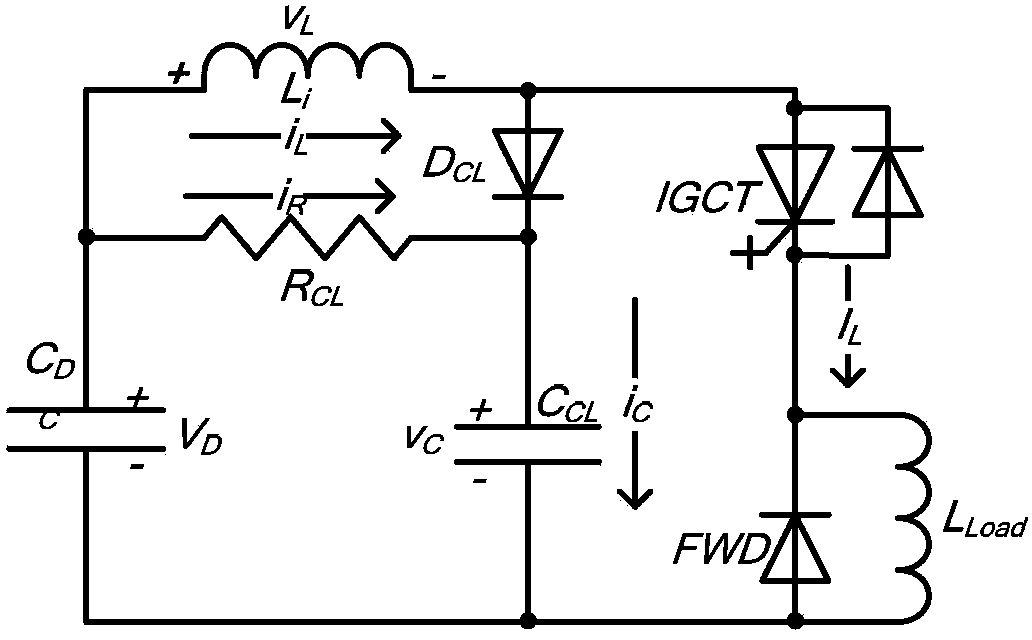
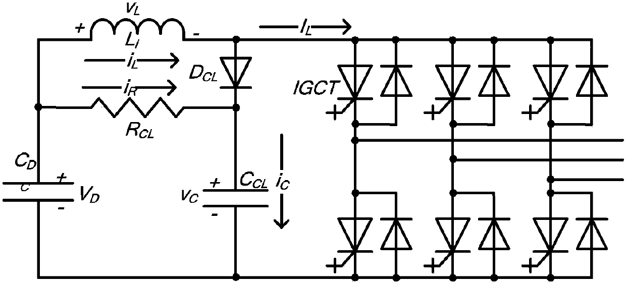
[0040] see Figure 1 to Figure 3 As shown, the IGCT converter / test circuit includes a DC side circuit and a conversion circuit, and the conversion circuit includes one or more IGCT devices. The DC side circuit includes a DC capacitor C DC , snubber inductance L i , clamping diode D CL , clamp capacitor C CL and clamp resistor R CL ; DC capacitance C DC The positive terminal of the snubber inductor L is connected i One terminal and the clamping resistor R CL One end of the snubber inductance L i The other end of the clamping diode D is connected CL positive terminal, the clamping resistor R CL The other end of the clamping diode D is connected CL Negative, clamping diode D CL The negative terminal of the clamp capacitor C is connectedCL One end of the clamping capacitor C CL Connect the other end of the DC capacitor C DC The negative pole of the conversion circ...


PUM


Abstract

The invention discloses a direct current side circuit of an IGCT (integrated gate commutated thyristor) converter/test circuit and a method for designing parameters of a clamp capacitor and a clamp resistor of the direct current side circuit. The direct current side circuit comprises a DC capacitor, a buffer inductor, a clamp diode, the clamp capacitor and the clamp resistor, wherein a positive electrode of the DC capacitor is connected with one end of the buffer inductor and one end of the clamp resistor, the other end of the buffer inductor is connected with a positive electrode of the clamp diode, the other end of the clamp resistor is connected with a negative electrode of the clamp diode, the negative electrode of the clamp diode is connected with one end of the clamp capacitor, and the other end of the clamp capacitor is connected with a negative electrode of the DC capacitor. The direct current side circuit disclosed by the invention is based on circuit principles, analyzes various states in the overall buffering and the working process of a clamp circuit in detail, derives the method for designing the parameters of the clamp capacitor and the clamp resistor according to differential expressions of various working states, thereby being more complete in theory, wider in application range and more accurate in parameter.

Description

technical field [0001] The invention relates to the technical field of power electronics, in particular to a parameter design method for a DC side circuit of an IGCT (integrated gate commutated thyristor) converter / test circuit and its clamping capacitance and clamping resistance. Background technique [0002] As a new type of power semiconductor device, IGCT has the advantages of high blocking voltage, large on-state current, low loss and high reliability, and has a good application prospect. However, the IGCT device also has certain shortcomings: the allowable current conversion rate di / dt of the IGCT itself is not very high. Therefore, in practical applications, a series snubber inductor is needed to limit the current conversion rate di / dt flowing through the device during turn-on and short-circuit. dt. Since there are stray inductances in the line, when the IGCT is turned off, the combined effect of the snubber inductance and the stray inductance will make the IGCT bear...

Claims


Application Information

Patent Timeline
IPC IPC(8): H02M1/32G01R31/26
Inventor 李宁王跃张长松王兆安
Owner XI AN JIAOTONG UNIV
Why Eureka
Try Eureka