Liquid crystal display device

一种液晶显示装置、液晶组合物层的技术,应用在液晶材料、光学、仪器等方向,能够解决电压保持率增加、取向不均、烧屏显示不良等问题,达到防止降低、防止白斑的效果

Active Publication Date: 2013-11-20
DIC CORP
View PDF7 Cites 13 Cited by
  • Summary
  • Abstract
  • Description
  • Claims
  • Application Information

AI Technical Summary

Problems solved by technology

[0016] The present invention provides a color filter using a specific liquid crystal composition and a specific pigment to prevent a decrease in the voltage retention rate (VHR) and an increase in the ion density (ID) of the liquid crystal layer, and to solve white spots, uneven orientation, Liquid crystal display devices with poor display problems such as screen burn-in

Method used


Image

  • Liquid crystal display device
  • Liquid crystal display device
  • Liquid crystal display device

Examples


Embodiment 1~4)

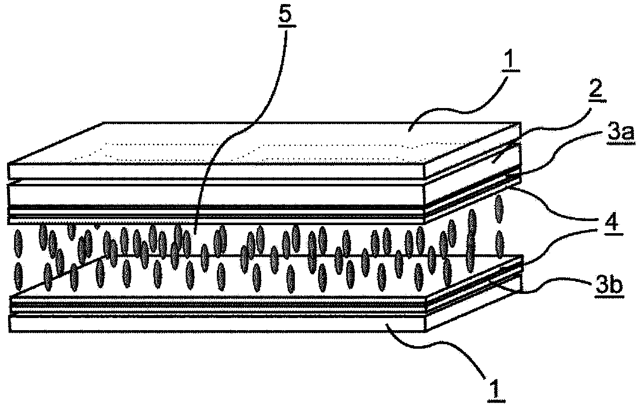
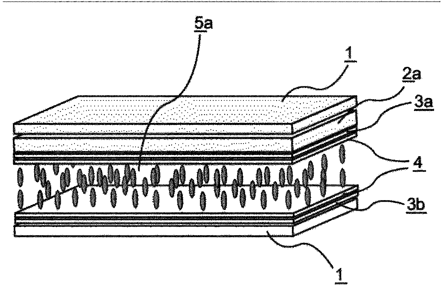
[0260] The first and second substrates are made into electrode structures, and vertical alignment films are formed on the opposite sides of each, and then subjected to weak rubbing treatment to form a VA unit. The first and second substrates are sandwiched between the table 2 The liquid crystal composition 1 with negative dielectric anisotropy is shown. Next, the color filters 1 to 4 shown in Table 1 were used to make a liquid crystal display device of Example 1 (d gap =3.5μm, oriented film SE-5300). The VHR and ID of the obtained liquid crystal display device were measured. In addition, the burn-in evaluation of the obtained liquid crystal display device was performed. The results are shown in Table 3.

[0261] [Table 2]

[0262]

[0263] [table 3]

[0264]

[0265] The liquid crystal display devices of Examples 1 to 4 can realize high VHR and small ID. In addition, there is no afterimage in the burn-in evaluation, or even if there is, it is a very small allowable level.

Embodiment 5~12)

[0288] The negative dielectric anisotropic liquid crystals shown in Table 10 were sandwiched in the same manner as in Example 1, and the color filters shown in Table 1 were used to prepare liquid crystal display devices of Examples 5 to 12, and the VHR and ID were measured. In addition, the burn-in evaluation of the liquid crystal display device was performed. The results are shown in Tables 11 and 12.

[0289] [Table 10]

[0290]

[0291] [Table 11]

[0292]

[0293] [Table 12]

[0294]

[0295] The liquid crystal display devices of Examples 5 to 12 can realize high VHR and small ID. In addition, there is no residual image in the burn-in evaluation, or even if there is a very small allowable level.

Embodiment 13~28

[0297] In the same manner as in Example 1, the negative dielectric anisotropic liquid crystals shown in Table 13 were sandwiched, and the color filters shown in Table 1 were used to prepare liquid crystal display devices of Examples 13 to 28, and the VHR and ID were measured. In addition, the burn-in evaluation of the liquid crystal display device was performed. The results are shown in Tables 14-17.

[0298] [Table 13]

[0299]

[0300] [Table 14]

[0301]

[0302] [Table 15]

[0303]

[0304] [Table 16]

[0305]

[0306] [Table 17]

[0307]

[0308] The liquid crystal display devices of Examples 13 to 28 can achieve high VHR and small ID. In addition, there is no residual image in the burn-in evaluation, or even if there is a very small allowable level.


PUM


Abstract

This invention relates to a liquid crystal display device using a color filter which uses a specific liquid crystal composition and a specific pigment. The present invention provides a liquid crystal display device which prevents decreases in voltage holding ratio (VHR) of a liquid crystal layer and increases in ion density (ID), and solves the problem of display defects such as white spots, uneven alignment, and burn-in. This liquid crystal display device is characterized by preventing decreases in the voltage holding ratio (VHR) of a liquid crystal layer and increases in ion density (ID), and by suppressing the occurrence of display defects such as burn-in, and in particular is useful in VA-mode and PSVA-mode liquid crystal display devices for active matrix driving, and can be applied in liquid crystal display devices such as liquid crystal TVs, monitors, mobile phones and smart phones.

Description

Technical field [0001] The present invention relates to a liquid crystal display device. Background technique [0002] Starting from clocks and calculators, liquid crystal display devices have been used in various household electrical appliances, measuring equipment, automotive panels, word processors, electronic notebooks, printers, computers, and televisions. As a liquid crystal display method, the representative liquid crystal display method can include TN (twisted nematic) type, STN (super twisted nematic) type, DS (dynamic light scattering) type, GH (guest-host) type, IPS (plane switching) Type, OCB (optical compensation birefringence) type, ECB (voltage controlled birefringence) type, VA (vertical orientation) type, CSH (color super vertical) type or FLC (ferroelectric liquid crystal), etc. In addition, as a driving method, the conventional method has evolved from static driving to multiplex driving. The simple matrix method and the recent active matrix (AM) method using T...

Claims


Application Information

Patent Timeline
Patent Type & Authority Applications(China)
IPC IPC(8): G02F1/1335C09K19/12C09K19/14C09K19/16C09K19/18C09K19/20C09K19/30C09K19/32C09K19/34G02B5/20G02F1/13
CPCC09K19/42C09K2019/3075C09K2019/3021C09K19/20C09K2019/3037G02F1/133514C09K2019/3016C09K2019/0466C09K2019/301C09K2019/304G02B5/201C09K2019/3078C09K19/322C09K2019/3009C09K2019/123C09K2019/3004C09K2019/0448C09K2019/3425C09K2019/521C09K19/04C09K19/06G02B5/20G02F1/1335
Inventor 金亲昌和竹内清文木村亮船仓省二岛田胜德
Owner DIC CORP
Why Eureka
Try Eureka