
Soil turning and stubble burying machine

A technology for turning soil and shoveling soil, which is applied to harvesters, soil preparation machines, crop processors, etc., can solve the problems of high power consumption of rotary tillage, no application of rice and wheat straw, and affecting the growth of subsequent rice.

Active Publication Date: 2013-11-27
徐云鹏
View PDF9 Cites 1 Cited by
  • Summary
  • Abstract
  • Description
  • Claims
  • Application Information

AI Technical Summary

Problems solved by technology

With the development of urbanization in southern Jiangsu, a large number of farmers have left the countryside to go to towns, and a large amount of rice and wheat straw has not found a reasonable way out. The government has adopted policies to guide farmers to return all straw to the field and replace the original medium-sized tractors with high-horsepower tractors. Use the rotary tillage straw returning machine to expand the plowing depth, but because the rotary tillage is to mix the straw and the soil in the plow layer and return it to the field, some straw will refloat to the surface in the subsequent flat field operations, which will directly affect the subsequent rice transplanting
Due to the high power consumption of rotary tillage, tractor operators often secretly adjust the depth of tillage to save fuel and reduce costs during rotary tillage operations, so that the straw is concentrated on the surface, which seriously affects the growth of subsequent rice crops.

Method used


Image

  • Soil turning and stubble burying machine
  • Soil turning and stubble burying machine
  • Soil turning and stubble burying machine

Examples


Embodiment Construction

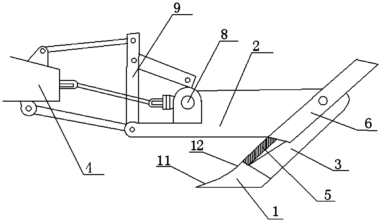
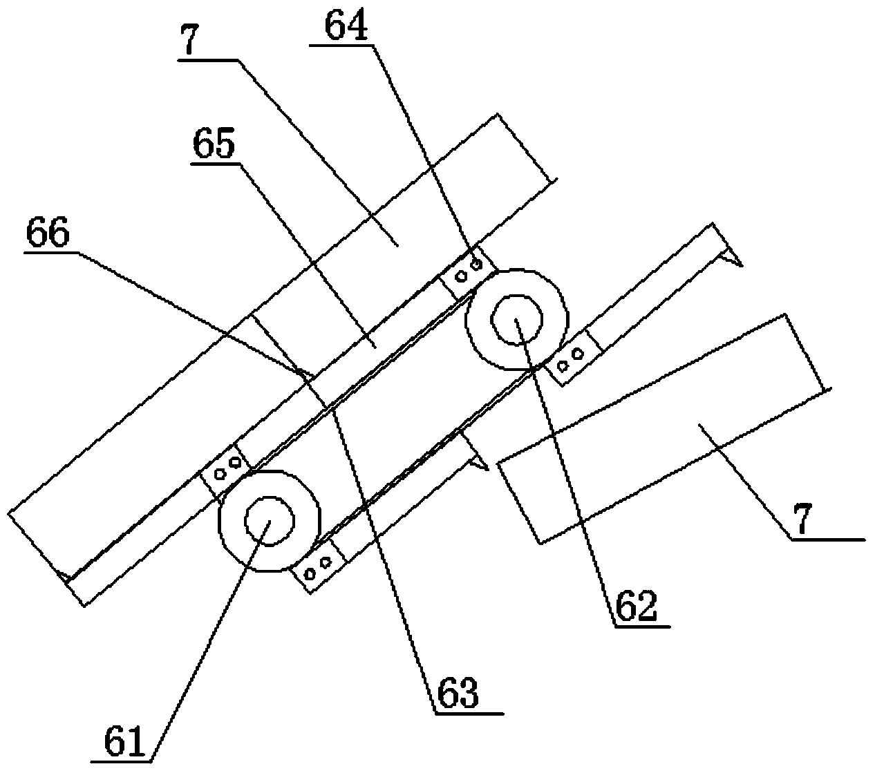
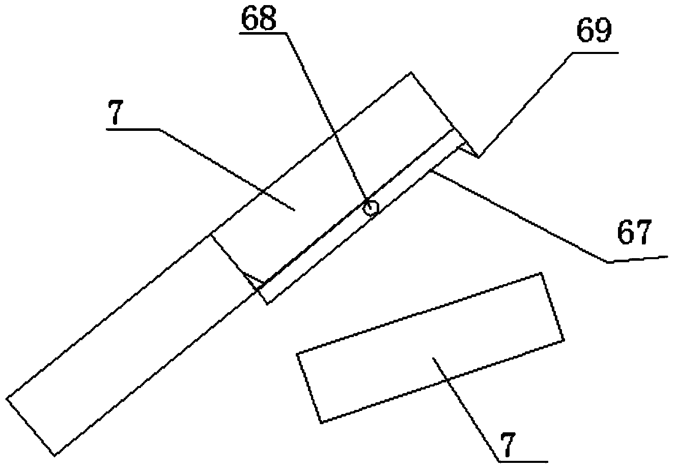
[0036] Such as figure 1 , figure 2 and image 3Shown, a kind of stubble turning machine is characterized in that: taking the direction of use as a reference, it includes at least one soil blade 1 arranged horizontally with a certain width and a traction frame 2 arranged above the soil blade, each Both sides of each soil shovel are respectively fixedly connected with a connection seat 3, and the connection seat is fixed on the traction frame; the front end of the traction frame is connected with the external traction device 4, and the oblique rear of the shovel The top is provided with a soil guide plate 5 and a tiller 6 in turn, and the external traction device can drive the traction frame to move horizontally, and drive the shovel knife to scoop up the plow layer soil, so that the scooped up plow layer soil 7 along the The soil guide plate is transported to the tiller; the traction frame is provided with a transmission mechanism 8, and the transmission mechanism can output...


PUM


Abstract

The invention discloses a soil turning and stubble burying machine which comprises at least one shovel knife and a traction frame, wherein the shovel knife has a certain width and is horizontally arranged; the traction frame is arranged above the shovel knife; the two sides of each shovel knife are respectively fixed on the traction frame by a connecting seat; the front end of the traction frame is connected with an external traction device; a soil guide plate and a soil turning device are sequentially arranged above the inclined rear of the shovel knife; the traction frame is driven to make horizontal motion by the external traction device; the external traction device can drive the shovel knife to scoop up the soil of a plough layer and enable the scooped soil of the plough layer to be sent onto the soil turning device along the soil guide plate; the traction frame is provided with a transmission mechanism which can output power so as to drive the soil turning device to overturn, so that the soil, conveyed to the upper part of the soil turning device, of the plough layer can be overturned and covered on the scooped ground surface. The soil turning and stubble burying machine can maintain the granular structure of the soil to the utmost extent while deeply burying full amount of straw and returning the straw to field, thus being especially beneficial to promoting the development of environment-friendly agriculture; the straw burning is replaced by burying via the machine, so that the agriculture carbon emission is reduced, and the agricultural sustainable development is promoted.

Description

technical field [0001] The invention relates to an agricultural machine, in particular to a stubble turning machine. Background technique [0002] The traditional land plowing technology has a history of more than 5,000 years. Modern plowing technology and plowing plows are essentially the same as traditional plows, except that some optimizations have been made on the surface of the plow body. The principle of plowing technology is to turn the plow layer soil to one side through a curved surface after shoveling the soil to achieve plowing. During the plowing process the surface soil is moved to one side by a distance of 30-35 cm, so the plowed field produces furrows. In the paddy field rotation area, when transplanting rice seedlings in the paddy field, it is necessary to ensure that the field surface is flat, so the plowed paddy field must be leveled manually or mechanically, which is laborious and laborious. In the past 20 years, plowing has basically withdrawn from the ...

Claims


Application Information

Patent Timeline
IPC IPC(8): A01B35/02A01D82/00
CPCY02P60/20
Inventor 徐云鹏
Owner 徐云鹏
Learn More