Machining method of valve seat of relief valve

A technology of overflow valve seat and processing method, which is applied in the field of overflow valve seat processing, can solve problems such as unstable working pressure, affecting the performance of the whole machine, and overflow valve leakage, so as to improve production efficiency and reduce production cost , Improve the effect of sealing performance

Active Publication Date: 2013-11-27
龙工(上海)精工液压有限公司
View PDF6 Cites 4 Cited by
  • Summary
  • Abstract
  • Description
  • Claims
  • Application Information

AI Technical Summary

Problems solved by technology

[0003] The technical problem to be solved by the present invention is to provide a simple, wide application range, high processing precision, and low production cost overflow valve seat processing method, which solves the leakage in the current various overflow valves. Problems that lead to unstable working pressure and affect the performance of the whole machine

Method used


Image

  • Machining method of valve seat of relief valve
  • Machining method of valve seat of relief valve
  • Machining method of valve seat of relief valve

Examples


Embodiment 1

[0025] The invention is a method for processing a valve seat of an overflow valve, which specifically includes the following steps:

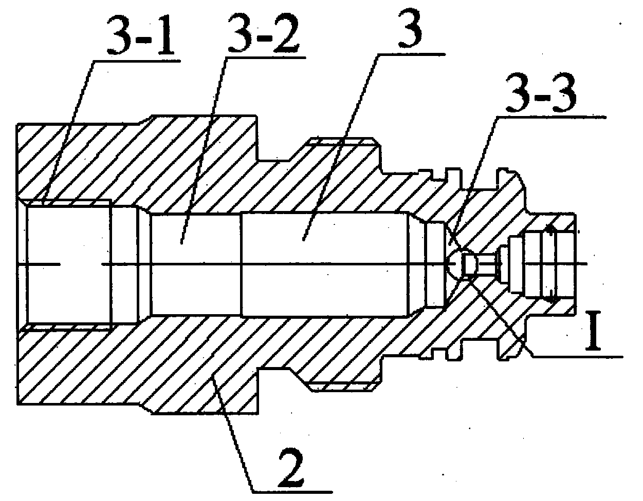
[0026] Step 1: If figure 1 Shown is a structural schematic diagram of the relief valve seat. The valve seat 1 of the overflow valve is turned with a CNC lathe. According to the requirements of the drawing, a rough hole 3 is first drilled on the valve seat 1 of the overflow valve with a φ9 drill bit, and the drilling depth is 45.8mm. The rotating speed of the drill bit is 1500r / min, the feed speed of the drilling bit is 140mm / min, and another φ12.5 tapping drill bit is used to process the threaded bottom hole 3-1 at the bottom of the rough hole 3, and the rotating speed of the tapping bit is is 1000r / min, the feed speed of the tapping drill is 120mm / min, and an enlarged hole 3-2 is formed by a boring tool in the middle section of the rough hole 3, and the enlarged hole 3-2 is bored to φ10.8. The depth is 44mm, the rotating speed of the boring t...

Embodiment 2

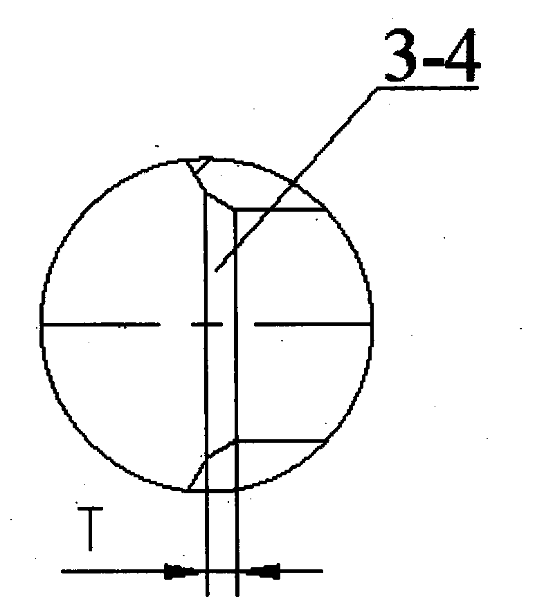
[0033] The invention relates to a method for processing a valve seat of an overflow valve. The rotating speed of the drilling drill is 1800r / min, the feeding speed of the drilling drill is 160mm / min, the rotating speed of the tapping drill is 1200r / min, and the tapping drill The feeding speed of the boring tool is 140mm / min, the rotating speed of the boring tool is 1800r / min, and the feeding speed of the boring tool is 160mm / min. The roughness of the tapered hole 3-3 is Ra1.6. Wherein, the rotating speed of the milling cutter is 3000n / min, and the feed speed of the milling cutter is 160mm / min. When using an internal and external cylindrical grinder to grind the enlarged hole 3-2, the rotating speed is 26000n / min, and the feed rate is 300mm / min.

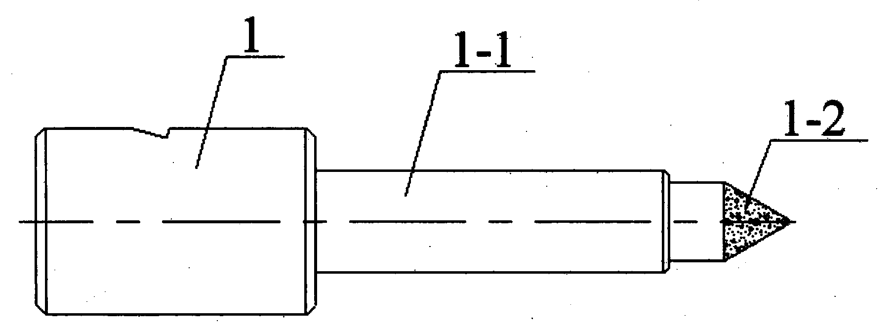
[0034] The coaxiality between the column rod 1-1 in the middle of the self-made grinding tool 2 and the top taper surface 1-2 is 0.005, and the roundness of the taper hole thus processed is 0.008mm. The roughness of the small frustu...

Embodiment 3

[0037]The invention relates to a method for processing a valve seat of an overflow valve. The rotating speed of the drilling drill is 1650r / min, the feeding speed of the drilling drill is 150mm / min, the rotating speed of the tapping drill is 1100r / min, and the tapping drill The feeding speed of the boring tool is 130mm / min, the rotating speed of the boring tool is 1650r / min, and the feeding speed of the boring tool is 150mm / min. The roughness of the tapered hole 3-3 is Ra2.4. Wherein, the rotational speed of the milling cutter is 2800n / min, and the feed speed of the milling cutter is 140mm / min. When using an internal and external cylindrical grinder to grind the enlarged hole 3-2, the rotating speed is 23000n / min, and the feed speed is 250mm / min.

[0038] The coaxiality between the column rod 1-1 in the middle of the self-made grinding tool 2 and the top taper surface 1-2 is 0.004, and the roundness of the taper hole thus processed is 0.006mm. The roughness of the small frus...


PUM

PropertyMeasurementUnit
Circularityaaaaaaaaaa

Abstract

The invention discloses a machining method of a valve seat of a relief valve. The machining method of the valve seat of the relief valve is characterized by comprising performing turning machining on the valve seat of the relief valve through a numerical control lathe, wherein the turning machining comprises drilling a rough hole in the valve seat of the relief valve through a drilling bit, machining a thread bottom hole at the bottom of the rough hole through a tapping bit and forming an expanded hole in the middle section of the rough hole through boring cutter machining; performing finish machining on the top of the rough hole through a milling cutter to form a tapered hole; performing grinding machining on the expanded hole through internal and external circular grinding machines; machining the top of the tapered hole through a self-made grinding tool and performing grinding and polishing processing in a low rotating speed and rapid feeding mode and a low rotating speed and slow feeding mode to form a small frustum. The machining method of the valve seat of the relief valve has the advantages of being wide in applicable range, high in machining accuracy, low in production cost, high in production efficiency and the like.

Description

technical field [0001] The invention relates to a method for processing a valve seat of an overflow valve, belonging to the innovative field of processing technology of hydraulic components. Background technique [0002] Most of the actuators in the existing excavators are controlled by multi-way valves, and the overflow valve is an indispensable part of the multi-way valve. It can maintain the load state of the working device, and when the working device is subjected to unexpected loads, it can quickly The opening pressure plays a role in protecting the hydraulic system of the whole machine. The processing of the overflow valve seat is the key technology, and its key performance lies in sealing to ensure stable working pressure. At present, the pressure is unstable during the working process of various relief valves, which leads to unstable operation of the oil cylinder and affects the performance of the whole machine. In order to meet the processing accuracy and cylindri...

Claims


Application Information

Patent Timeline
Patent Type & Authority Applications(China)
IPC IPC(8): B23P15/00
Inventor 刘彬李志勇贾金保张丽琴焦永昌
Owner 龙工(上海)精工液压有限公司
Why Eureka
Try Eureka