Check patentability & draft patents in minutes with Patsnap Eureka AI!

Guide rail and sliding block mechanism of sliding block type hydrostatic guide rail

A hydrostatic guide rail and slider type technology, used in metal processing machinery parts, large fixed members, metal processing equipment, etc., can solve the problems of various structures, affecting the movement accuracy of machine tools, and poor vibration absorption.

Inactive Publication Date: 2013-11-27
芜湖陀曼精机科技有限公司
View PDF6 Cites 2 Cited by
  • Summary
  • Abstract
  • Description
  • Claims
  • Application Information

AI Technical Summary

Problems solved by technology

However, this kind of guide rail has inherent defects. Because it is rolling to transmit linear motion, the vibration absorption is poor, and there is a difference between static friction resistance and dynamic friction resistance, which affects the motion accuracy of the machine tool to a certain extent, especially when the cutting force changes greatly. , the machine tool with frequent speed changes will affect the machining accuracy of the machine tool
Therefore, many machine tool manufacturers are designing and manufacturing static pressure guide rails by themselves, but the structures are varied, and it is impossible to form standardized, serialized, and generalized standard parts, which seriously hinders the promotion and improvement of static pressure technology. Designed the slider type closed hydrostatic guide rail slider, which created conditions for the standardization and serialization of hydrostatic guide rails

Method used


Image

  • Guide rail and sliding block mechanism of sliding block type hydrostatic guide rail
  • Guide rail and sliding block mechanism of sliding block type hydrostatic guide rail
  • Guide rail and sliding block mechanism of sliding block type hydrostatic guide rail

Examples


Embodiment Construction

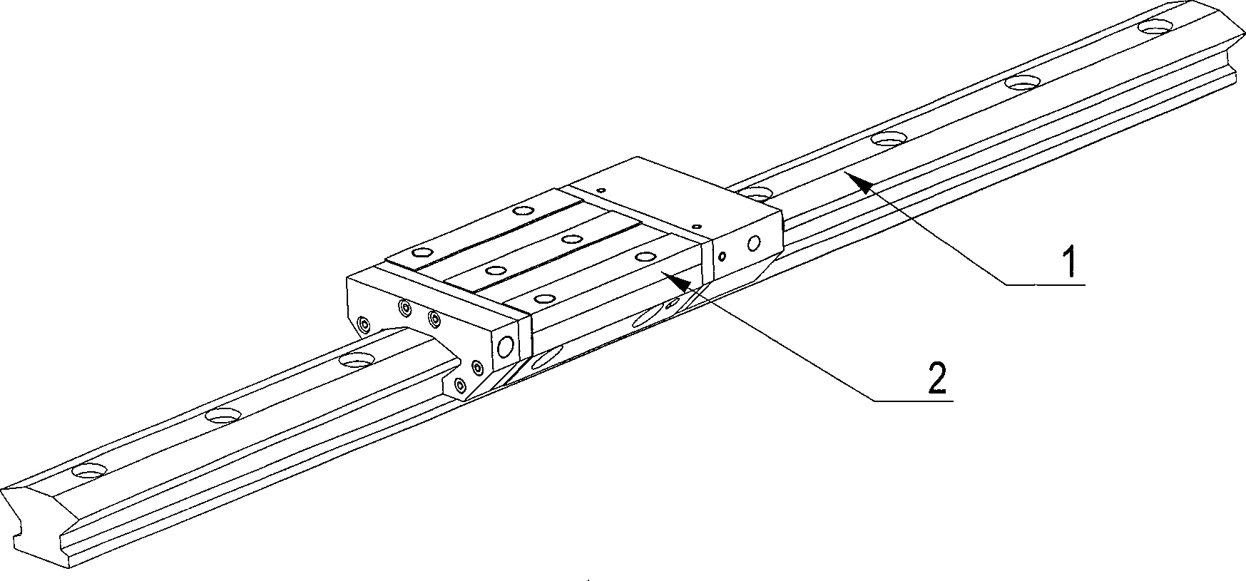
[0012] The specific embodiment of the invention will be described in conjunction with the accompanying drawings.

[0013] like figure 1 As shown, the present invention is composed of a guide rail 1 and a slider 2, wherein the hydrostatic slider 2 is as Figure 2-4 As shown, its inner shape is a downward concave groove, and there are two bearing surfaces on the upper and lower sides of the groove wall, and the upper bearing surface is opened with large-area pressure oil chambers 6 and 8, and its horizontal angle is 20°, effectively The bearing capacity of the static pressure guide rail is improved; there are small-area pressure oil chambers 7 and 9 on the lower bearing surface, and the horizontal angle is 40°, which effectively improves the rigidity of the slider.

[0014] The load-bearing surface of the guide rail matches the load-bearing surface of the slider and has a certain gap, and the gaps of the static pressure guide rails of different specifications are different.

...


PUM


Abstract

The invention discloses a guide rail and sliding block mechanism of a sliding block type hydrostatic guide rail, and relates to parts of the sliding block type hydrostatic guide rail. The guide rail and sliding block mechanism comprises a guide rail with bearing faces at different angles. The horizontal angle of the upper bearing face of the guide rail is 20 degrees. The angle of the lower bearing face of the guide rail is 40 degrees. The guide rail and sliding block mechanism further comprises a sliding block with different oil cavity areas. The inner shape of the sliding block is a U-shaped groove with a downward opening. The upper portion of the groove wall and the lower portion of the groove wall are respectively provided with two bearing faces. A large pressure oil cavity is formed in each upper bearing face. A small pressure oil cavity is formed in each lower bearing face. The bearing capacity of the hydrostatic guide rail is effectively improved. The horizontal angles of the bearing faces of the sliding block are consistent with the horizontal angles of the bearing faces of the guide rail. The sliding block and the bearing faces of the guide rail are matched, and a certain gap is reserved between the sliding block and the bearing faces of the guide rail. Four oil inlet holes are formed in the sliding block, pressure oil can enter the oil cavities through the oil inlet holes, a pressure oil film is formed between the sliding block and the guide rail, and the hydrostatic effect is generated. Oil returning grooves are formed in the peripheries of the pressure oil cavities and communicated with an oil sucking pump to guarantee that the returned oil in the pressure oil cavities is in the negative pressure, and the hydrostatic stability is effectively improved.

Description

technical field [0001] The invention relates to a standard component used in conjunction with a high-precision or heavy-duty machine tool, in particular to a slide block type static pressure guide rail. Background technique [0002] In medium and large-scale and high-precision machine tools, the roller linear guideway (slider type) developed in the past ten years is widely used, and this kind of guideway has formed standardized, serialized and generalized products. However, this kind of guide rail has inherent defects. Because it is rolling to transmit linear motion, the vibration absorption is poor, and there is a difference between static friction resistance and dynamic friction resistance, which affects the motion accuracy of the machine tool to a certain extent, especially when the cutting force changes greatly. , The machine tool with frequent speed changes will affect the machining accuracy of the machine tool. Therefore, many machine tool manufacturers are designing ...

Claims


Application Information

Patent Timeline
IPC IPC(8): B23Q1/01B23Q1/38
Inventor 俞朝杰裴崇文吕潮斌
Owner 芜湖陀曼精机科技有限公司
Features
  • R&D
  • Intellectual Property
  • Life Sciences
  • Materials
  • Tech Scout
  • Unparalleled Data Quality
  • Higher Quality Content
  • 60% Fewer Hallucinations
Learn More