Side core-pulling structure for die with one side mold insert and one side ejector pin

A side core-pulling and inserting technology is applied to the structural field of product molds, which can solve the problems of low production efficiency, time-consuming and laborious installation and processing, and high mold production costs, and achieve the effects of high production efficiency, low production costs, and simple structure.

Inactive Publication Date: 2013-11-27
WUXI CITY NEW DISTRICT WEICHUANGLI MOLD FACTORY
View PDF0 Cites 0 Cited by
  • Summary
  • Abstract
  • Description
  • Claims
  • Application Information

AI Technical Summary

Problems solved by technology

[0002] The mold of a product with a through hole on one side and multiple small holes on the other side. Specifically, the hole type inserts are set on one side of the cavity of the mold, and the corresponding number of thimble inserts are set on the other side. When demolding , the hole-shaped insert is driven by the inclined guide column to complete the core-pulling, and the end of the thimble insert is fastened in the positioning groove between the thimble connection block and the row block, and then the connection block is fastened to connect the row block. Driven by the side inclined guide post, the bit block completes the core pulling. The whole structure needs two inclined guide posts. Since the installation and processing of the inclined guide posts are time-consuming and laborious, the manufacturing cost of the entire mold is high and the production efficiency is low.

Method used


Image

  • Side core-pulling structure for die with one side mold insert and one side ejector pin

Examples


Embodiment Construction

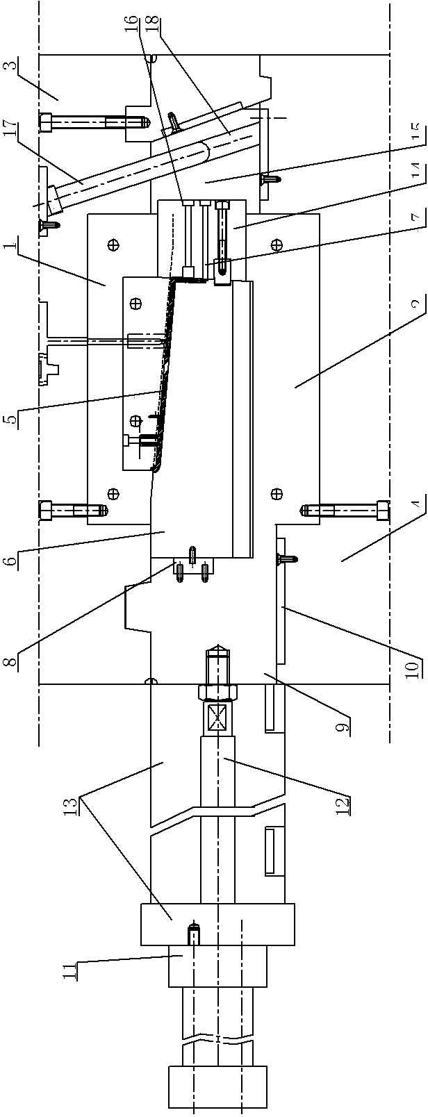
[0008] See figure 1 , which includes a front mold 1, a rear mold 2, a plate 3, and a plate B 4, a cavity 5 is formed between the front mold 1 and the rear mold 2, the hole insert 6 is located on the corresponding side of the cavity 5, and the thimble insert 7 The side is pushed against the cavity 5 of the corresponding side, and the end of the hole insert 6 is embedded in the side connecting block 8, and the connecting block 8 is fastened to the inner side of the linear positioning block 9, and the bottom end surface of the linear positioning block 9 supports On the upper plane of the wear-resistant block 10, the lower end plane of the wear-resistant block 10 is fastened to the B plate 4, and the outer side of the linear position block 9 is fastened to the piston rod 12 of the oil cylinder 11, and the oil cylinder 11 is fastened to the B plate through the oil cylinder seat 13. outside of plate 4. The end of the thimble insert 7 is fastened in the positioning groove 16 between...


PUM


Abstract

The invention provides a side core-pulling structure for a die with one side mold insert and one side ejector pin. The side core-pulling structure for the die with one side mold insert and one side ejector pin is simple, so the die has the advantages of a simple structure, low manufacturing cost, high installation efficiency and high production efficiency. The side core-pulling structure comprises a front mold, a rear mold, a plate A and a plate B, wherein a cavity is located between the front mold and the rear mold, a hole type mold insert is located in the cavity at a corresponding side, and an ejector pin mold insert laterally abuts against a corresponding side in the cavity. The side core-pulling structure is characterized in that the tail end of the hole type mold insert is embedded in a connecting block located at a same side as the hole type mold insert, the connecting block is fixedly connected with the inner side of a linear slide block, the bottom end face of the linear slide block is supported on the upper plane of a wear-resistant block, the lower end face of the wear-resistant block is fixedly connected with the plate B, the outer side of the linear slide block is fixedly connected with a piston rod of an oil cylinder, and the oil cylinder is fixed at the outer side of the plate B through an oil cylinder seat.

Description

technical field [0001] The invention relates to the structural technical field of product molds, in particular to the side core-pulling structure of one side insert and one side thimble mold. Background technique [0002] The mold of a product with a through hole on one side and multiple small holes on the other side. Specifically, the hole type inserts are set on one side of the cavity of the mold, and the corresponding number of thimble inserts are set on the other side. When demolding , the hole-shaped insert is driven by the inclined guide post to complete the core-pulling, and the end of the thimble insert is fastened in the positioning groove between the thimble connection block and the row block, and then the connection block is fastened to connect the row block. Driven by the side inclined guide pillars, the bit block completes the core pulling. The whole structure requires two inclined guide pillars. Since the...

Claims


Application Information

Patent Timeline
Patent Type & Authority Applications(China)
IPC IPC(8): B29C45/33B29C45/40
Inventor 吕应军
Owner WUXI CITY NEW DISTRICT WEICHUANGLI MOLD FACTORY
Why Eureka
Try Eureka