Injection mold device with heating device

A technology of injection mold and heating device, applied in the field of injection molding equipment, can solve the problems of reducing injection molding precision, inconvenience, and adversely affecting the production efficiency of enterprises, and achieves the effects of good sealing performance, convenient extraction and insertion, and reliable connection.

Inactive Publication Date: 2013-11-27
成都万顺达模具零件有限公司
View PDF0 Cites 1 Cited by
  • Summary
  • Abstract
  • Description
  • Claims
  • Application Information

AI Technical Summary

Problems solved by technology

[0004] In view of the above-mentioned complex plastic products, it is often inconvenient to open the movable mold and the fixed mold. The injection molding cannot be completed in one step, and the injection precision can only be reduced. The shape requirements are achieved through post-processing, which is not conducive to the production efficiency of the enterprise. In order to solve the problem of poor controllability of mold heat preservation and forced cooling heat transfer speed, the invention provides an injection mold device with a heating device

Method used


Image

  • Injection mold device with heating device

Examples


Embodiment 1

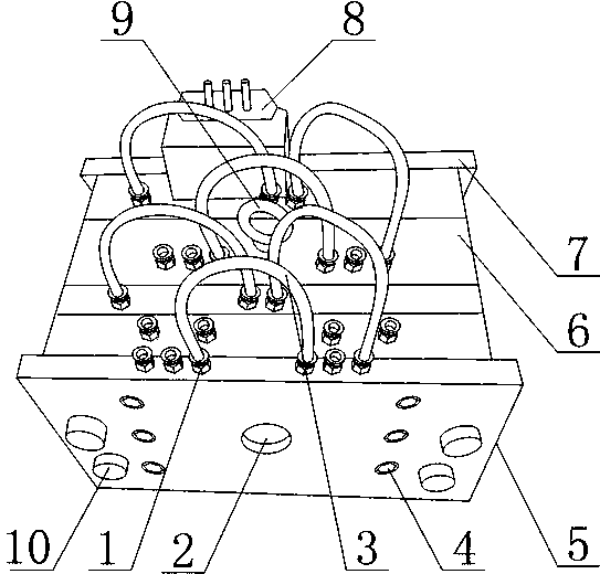
[0026] Such as figure 1 As shown, a kind of injection mold device with heating device comprises front baffle plate 5, a plurality of cavity plates 6 with cavities inside, rear baffle plate 7 and electric heater 8, and a plurality of said cavity plates 6 is located between the front baffle 5 and the rear baffle 7, and the front baffle 5, a plurality of the cavity plates 6, and the rear baffle 7 are stacked in sequence, and the front baffle 5, the plurality of cavity plates 7 Both the cavity plate 6 and the rear baffle 7 are provided with a plurality of flow passages communicating up and down, the front baffle 5 is also provided with injection holes 2, and the rear baffle 7 is also provided with exhaust holes. The electric heater 8 is arranged on the cavity plate 6 .

[0027] The set front baffle 5, multiple cavity plates 6 and rear baffle 7 are combined to form the cavity of the injection mold, and the cavity part is composed of front baffle 5, multiple cavity plates 6 and rea...

Embodiment 2

[0029] This embodiment is further defined on the basis of embodiment 1, as figure 1 As shown, it also includes drainage tube interfaces 1 whose number is twice the number of flow channels, and the drainage tube interfaces 1 are respectively arranged at the inlet and outlet of each flow channel.

[0030] The provided drainage tube interface 1 facilitates the connection between the flow channel and the external pipeline in the present invention.

[0031] It also includes a drainage tube 3, the drainage tube interface 1 is a common quick connector for gas and liquid, the drainage tube 3 is a plastic hose, and the free ends of the drainage tube 3 are fixedly connected to any two drainage tube interfaces 1 .

[0032] The set plastic hose and the gas-liquid shared quick connector are easy to pull out and insert, and the connection is reliable, and the sealing performance of the connection surface is good.

[0033] The front baffle plate 5, the plurality of cavity plates 6 and the c...


PUM


Abstract

The invention discloses an injection mold device with a heating device. The injection mold device comprises a front baffle plate (5), a plurality of cavity plates (6) provided with cavities formed in the inner sides, a rear baffle plate (7) and an electric heater (8), wherein the front baffle plate (5), the cavity plates (6) and the rear baffle plate (7) are provided with a plurality of flow passages of which the upper parts and the lower parts are communicated; the front baffle plate (5) is further provided with an injection molding hole (2); the rear baffle plate (7) is further provided with an exhaust hole. The injection mold device can adapt to mold opening of cavities in complex shapes, is conducive to improving injection molding precision of plastic products with complex shapes, and can eliminate and reduce follow-up reprocessing; with the flow passages and the electric heater, the injection mold device can well adapt to cooling speeds required to be kept in different plastic injection molding processes and requirements of mold temperature during injection molding, and is conducive to improving production efficiency of enterprises and product quality.

Description

technical field [0001] The invention relates to the field of injection molding equipment, in particular to an injection mold device with a heating device. Background technique [0002] Injection molding is a processing method used in the mass production of certain parts with complex shapes. Specifically, it refers to injecting heated and melted materials into a mold cavity under high pressure, and after cooling and solidifying, molded products are obtained. Injection mold is a tool for producing plastic products, which gives plastic products complete structure and precise dimensions. [0003] Existing injection mold is made up of two parts of movable mold and fixed mold, and movable mold and fixed mold are closed to form gating system and mold cavity during injection molding, and movable mold and fixed mold are separated so that take out plastic product when mold is opened. However, due to the ever-changing shapes and structures of plastic products, plastic products with co...

Claims


Application Information

Patent Timeline
Patent Type & Authority Applications(China)
IPC IPC(8): B29C45/73B29C45/26
Inventor 艾俊钟树军李强
Owner 成都万顺达模具零件有限公司
Why Eureka
Try Eureka