Device for conveying steel pipe transversely falling step by step

A technology of conveying device and steel pipe, which is applied to conveyor objects, transportation and packaging, etc., can solve the problems of complicated conveying equipment, high manufacturing cost, and difficulty in rolling down one by one. simple structure

Inactive Publication Date: 2013-11-27
嘉兴永励精密钢管有限公司
View PDF5 Cites 24 Cited by
  • Summary
  • Abstract
  • Description
  • Claims
  • Application Information

AI Technical Summary

Problems solved by technology

[0003] During the production and manufacturing process of steel pipes, it is often necessary to carry out lateral movement and transportation of steel pipes one by one, and the equipment for providing this kind of horizontal transportation of steel pipes is generally more complicated, often requiring multiple sets of parallel conveying chains along the steel pipe axis. Use the electronic control system to control the chain to drive the steel pipe for horizontal conveying, and if the steel pipe needs to be conveyed horizontally from a high place to a low place and finally loaded into the material rack, the conveying track needs to be inclined downward, and the conveying equipment is more complicated, and The manufacturing cost is bound to be high, and the cost of using this kind of conveying equipment is too high compared to steel pipe manufacturers.
[0004] Using the gravity of the steel pipe itself, it is a low-cost way to let the steel pipe tilt and roll from top to bottom. However, if the tilt angle is too large, or the guide rail of the tilted roll is too long, the steel tube will continue to accelerate under the action of gravity acceleration. Rolling down, there will be a large impact between the steel pipes, which will easily cause bruises on the steel pipes, the quality of the steel pipe products cannot be guaranteed, and it is also difficult to achieve rolling down one by one

Method used


Image

  • Device for conveying steel pipe transversely falling step by step
  • Device for conveying steel pipe transversely falling step by step

Examples


Embodiment Construction

[0023] The present invention will be further described below in conjunction with specific examples.

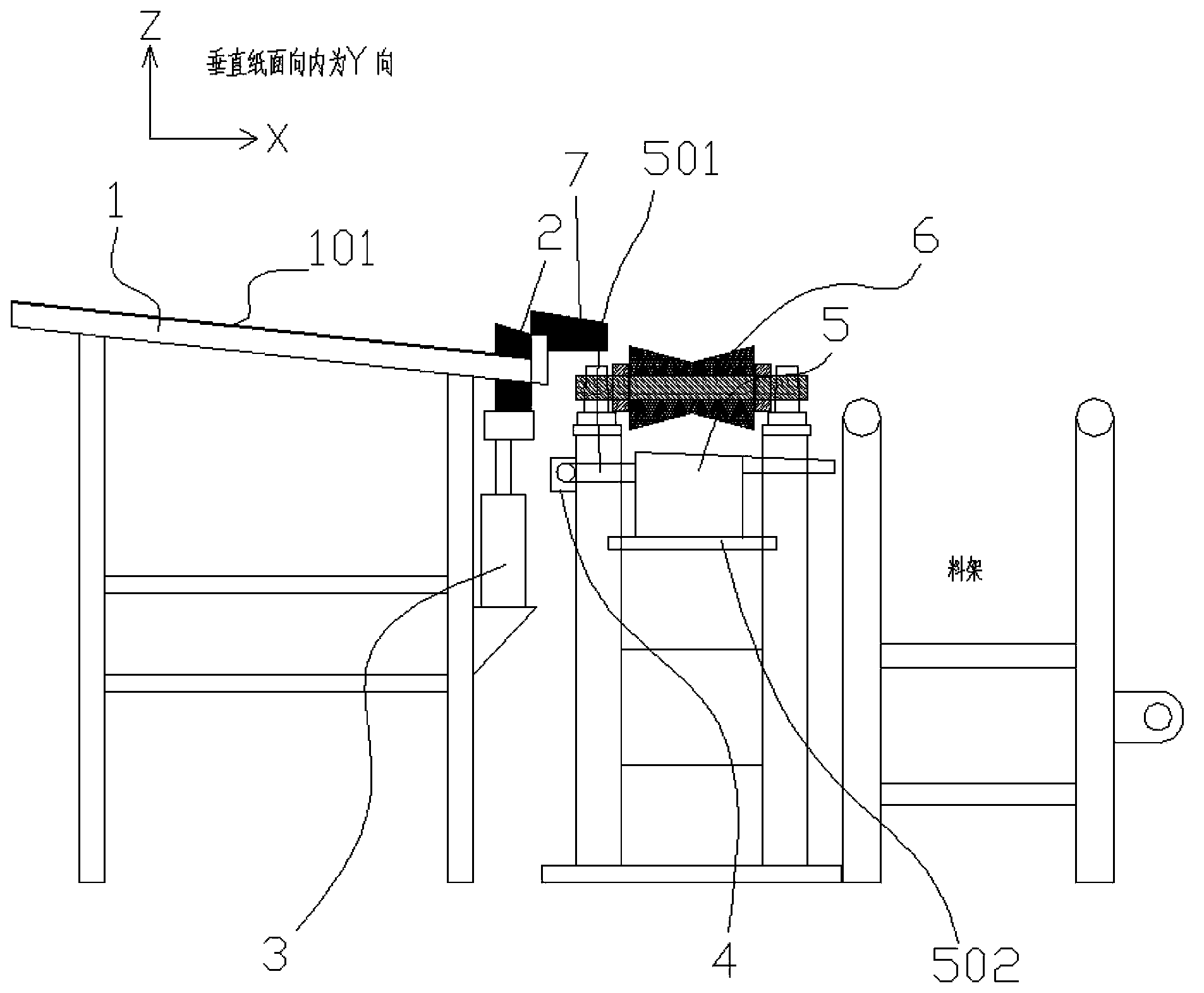
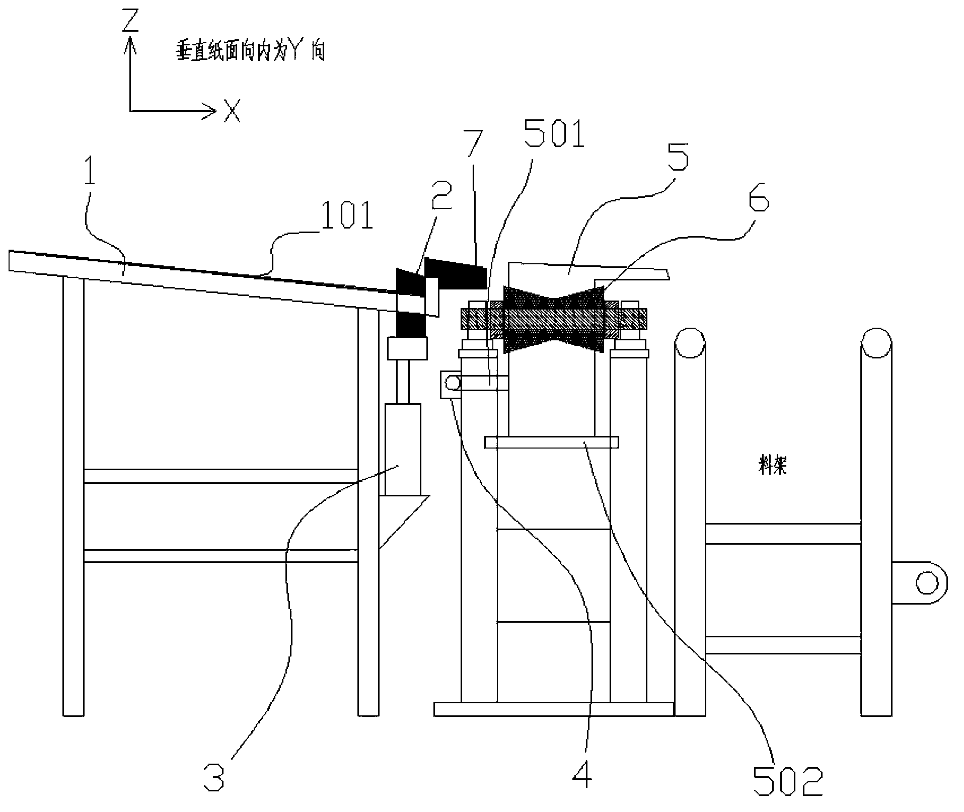
[0024] see figure 1 , assuming that the horizontal movement direction of the steel pipe is the X direction, the axial direction of the steel pipe is the Y direction, and the vertical upward direction is the Z direction; multiple sets of support and guide units are arranged in parallel along the Y direction, figure 1 In addition to the material rack, it and the structure indicate the support and guide unit on the rearmost side along the Y direction, but actually forward along the Y direction, that is, there are multiple sets of support and guide units in the direction perpendicular to the inward direction of the paper surface, which jointly support the steel pipe. undertake.

[0025] The support and guide unit includes: a rolling support rod 1 arranged obliquely downward along the X direction, a vertical cylinder 3 is arranged at the corresponding position at the lower end of ...


PUM


Abstract

The invention relates to a device for conveying a steel pipe transversely falling step by step. The device comprises rolling supporting rods which are obliquely placed downwards in the X direction, wherein vertical cylinders are arranged in the positions corresponding to the lower ends of the rolling supporting rods, and are connected with pushing blocks; the height of each pushing block is lower than that of the lower end of each rolling supporting rod, and the upper end surfaces of the pushing blocks are tilted downwards in the X direction; the lower ends of the rolling supporting rods are further connected with guide blocks; the guide blocks are positioned in front of the pushing blocks in the X direction, and the upper end surfaces of the guide blocks are tilted downwards in the X direction; ejector rods of the vertical cylinders are used for lifting up upwards; the front side of the upper end surface of each pushing block in the X direction and the rear side of the upper end surface of each guide block in the X direction are positioned in the positions at the same height; carrier roller support frames are arranged in front of the guide blocks in the X direction; rotating plates are arranged below carrier rollers, and the upper side edges of the carrier rollers are tilted downwards in the X direction; a horizontal cylinder is fixedly arranged on the carrier roller support frame at the rearmost end in the Y direction, and an ejector rod of the horizontal cylinder is connected with a long shaft; the long shaft is fixedly connected with the rotating plates, and the ejector rod of the horizontal cylinder contracts to drive the rotating plates to rotate around rotating shafts thereof, so as to lift up a steel pipe together and enable the steel pipe to roll down along the upper side edges of the rotating plates.

Description

technical field [0001] The invention relates to a steel pipe conveying device, in particular to a steel pipe horizontally falling step by step conveying device, which belongs to the technical field of steel pipe horizontal conveying. Background technique [0002] The steel pipe is used to transport fluid and powdery solids, exchange heat energy, and manufacture mechanical parts and containers. It is a kind of economical steel. Using steel pipes to manufacture building structure grids, pillars and mechanical supports can reduce weight, save 20-40% of metal, and realize factory-like mechanized construction. Because steel pipes are inseparable from human life and production activities, the production technology of steel pipe industry not only develops rapidly, but also introduces new ones. Steel pipe production occupies an irreplaceable position in the steel industry. [0003] During the production and manufacturing process of steel pipes, it is often necessary to carry out la...

Claims


Application Information

Patent Timeline
Patent Type & Authority Applications(China)
IPC IPC(8): B65G47/14
Inventor 刘正华
Owner 嘉兴永励精密钢管有限公司
Why Eureka
Try Eureka