Supercharge Your Innovation With Domain-Expert AI Agents!

Rail cleaning device for crane

A crane and track cleaning technology, applied in the direction of track system, transportation and packaging, load hanging components, etc., can solve the problems of burnt motor, wheel derailment, rollover, corrosion of wheel tread, etc.

Inactive Publication Date: 2013-11-27
ELEPHANT KING HEAVY IND
View PDF5 Cites 1 Cited by
  • Summary
  • Abstract
  • Description
  • Claims
  • Application Information

AI Technical Summary

Problems solved by technology

[0003] The track clearing devices currently used on various rail-type operating cranes are generally of the fixed steel plate type. The fixed track clearing device is bolted or welded to the frame of the traveling platform, and the lower steel plate of the track clearing device maintains a certain gap with the corner running track; When the trolley is moving forward, if there are iron pieces, gravel and other sundries on the track, the steel plate at the lower part of the track clearing device will push them away, so as to avoid the large walking resistance caused by the wheels pressing on the sundries, thereby avoiding The motor is overloaded and burned to avoid accidents such as possible wheel derailment. However, since the lower steel plate of the traditional fixed steel plate type track clearing device must maintain a certain gap with the top surface of the track, generally 5 ~ 10mm, so when the height of the rail top is less than 5 ~ When there are debris of 10mm, this track cleaning device cannot completely remove the debris on the rail top, which may cause accidents such as burning out the motor and wheel derailment; some debris will stick to the surface of the wheel, corrode the wheel tread or cause the wheel If the diameter increases, if the diameters of the wheels on both sides are different, it will cause the crane to run deflected, and eventually lead to accidents such as derailment or rollover of the crane

Method used


Image

  • Rail cleaning device for crane
  • Rail cleaning device for crane

Examples


Embodiment Construction

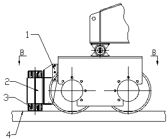
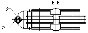
[0011] The crane track clearing device of the present invention will be described in further detail below in conjunction with the accompanying drawings and specific embodiments.

[0012] As shown in the figure, the crane rail clearing device of the present invention includes a guide tube 2 installed on the front end of the wheel through a mounting frame 1, and a hardwood stopper 3 whose outer diameter matches the inner surface of the guide tube 2 is provided in the guide tube 2. The lower end of stopper 3 freely falls on rail surface 4, and wherein guide pipe 2 cross-sectional shape is curved surface shape structure or water chestnut structure, and specifically guide pipe 2 cross-sectional shape can be square, rhombus, rectangle or circular hole etc., of course hardwood The outer profile of the stopper 3 should be adapted to the inner cavity profile of the guide tube 2, so that the hardwood stopper 3 can slide freely in the guide tube 2, and due to the self-weight of the hardwo...


PUM


Abstract

The invention discloses an accessory device for a crane, particularly discloses a rail cleaning device for the crane, and belongs to the technical field of crane machines. The rail cleaning device comprises a guiding pipe arranged at the front end of a wheel through a mounting rack, wherein the guiding pipe is internally provided with a hardwood link stopper the outer diameter of which is in clearance fit with the inner surface of the guiding pipe, and the lower end of the hardwood link stopper freely falls on a rail surface. Due to the adoption of the structure, the guiding pipe is arranged at the front end of the wheel through the mounting rack, and the guiding pipe is internally provided with the hardwood link stopper the outer diameter of which is in clearance fit with the inner surface of the guiding pipe, therefore the lower end of the hardwood link stopper freely falls on the rail surface, the rail cleaning device can always fit the top of a rail, sundries on the top of the rail are thoroughly cleared away, the rail cleaning device can adapt to the uneven top of the rail, the problem that a current general rail cleaning device can not fit the top of the rail is solved, the structure is simple, the cost is low, the rail is thoroughly cleaned, the reliability is high, the price is low, and the rail cleaning device is suitable for generally popularizing.

Description

[0001] technical field [0002] The invention relates to an accessory device for a crane, in particular to a rail clearing device for a crane, which belongs to the technical field of hoisting machinery. Background technique [0003] The track clearing devices currently used on various rail-type operating cranes are generally of the fixed steel plate type. The fixed track clearing device is bolted or welded to the frame of the traveling platform, and the lower steel plate of the track clearing device maintains a certain gap with the corner running track; When the trolley is moving forward, if there are iron pieces, gravel and other sundries on the track, the steel plate at the lower part of the track clearing device will push them away, so as to avoid the large walking resistance caused by the wheels pressing on the sundries, thereby avoiding The motor is overloaded and burned to avoid accidents such as possible wheel derailment. However, since the lower steel plate of th...

Claims


Application Information

Patent Timeline
Patent Type & Authority Applications(China)
IPC IPC(8): B66C13/00B66C7/00
Inventor 何先凡闫孟郝文文
Owner ELEPHANT KING HEAVY IND
Features
  • R&D
  • Intellectual Property
  • Life Sciences
  • Materials
  • Tech Scout
  • Unparalleled Data Quality
  • Higher Quality Content
  • 60% Fewer Hallucinations
Learn More