
Movable suspension bracket for power installation

A movable hanger and electric power technology, which is applied in the direction of hoisting device, transportation and packaging, load hanging components, etc., can solve the problems of unusable, inconvenient transfer, and large size of the hanger, so as to save space and facilitate transfer. Effect

Inactive Publication Date: 2013-11-27
STATE GRID CORP OF CHINA +1
View PDF5 Cites 5 Cited by
  • Summary
  • Abstract
  • Description
  • Claims
  • Application Information

AI Technical Summary

Problems solved by technology

[0002] The existing power installation movable hanger is a door-shaped hanger, that is, an electric hoist or a pulley is arranged on a door-shaped frame, but this kind of hanger is inconvenient for transportation due to its large volume, and there is also an L-shaped hanger, which is In order to maintain stability, this kind of hanger must fix the bottom on the car body, and it cannot be used in areas where vehicles cannot enter

Method used


Image

  • Movable suspension bracket for power installation
  • Movable suspension bracket for power installation

Examples


Embodiment Construction

[0016] The technical solutions of the present invention will be described in further detail below through specific embodiments.

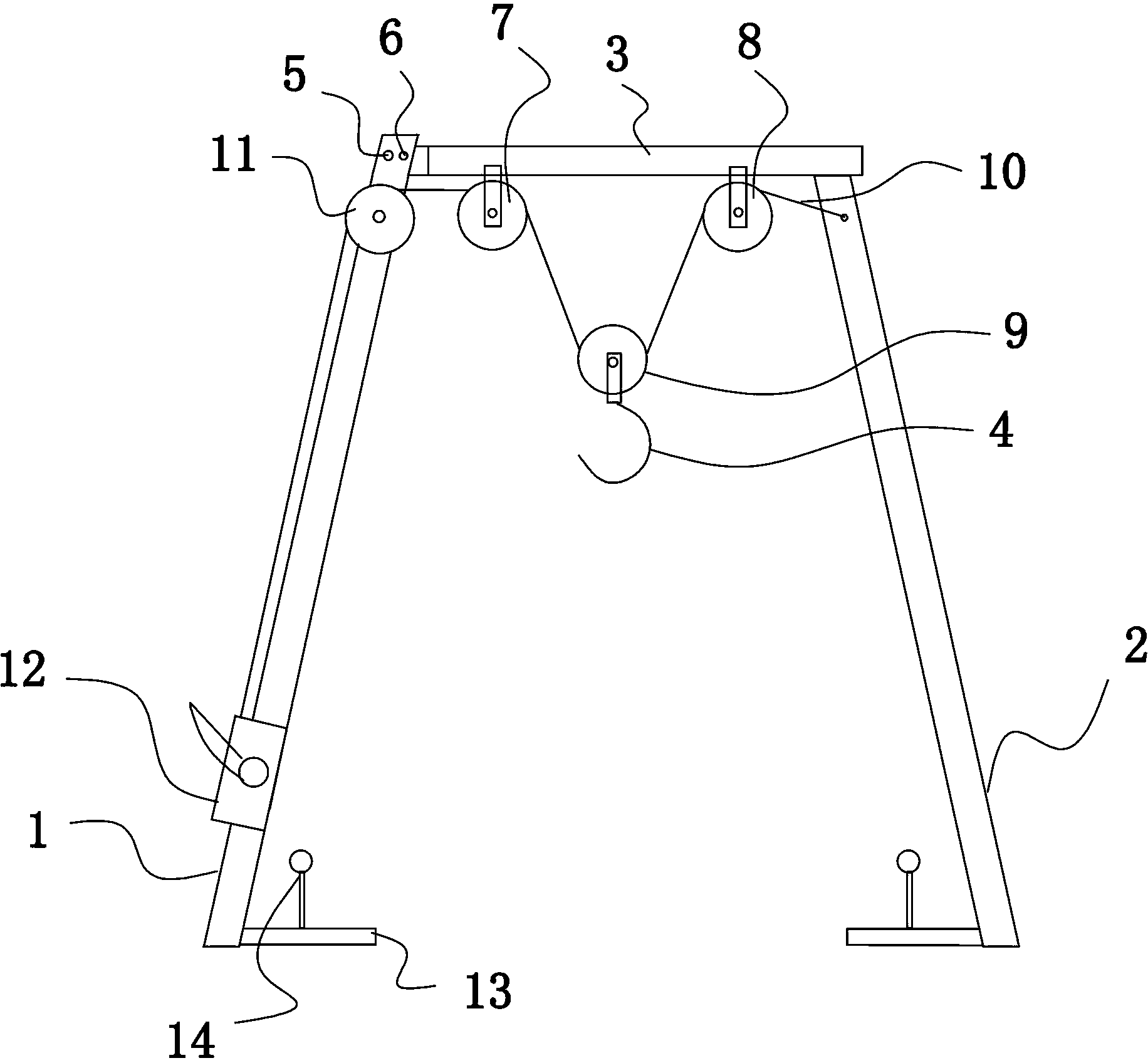
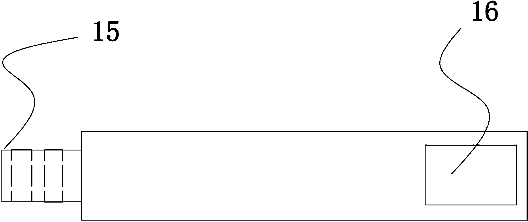
[0017] like figure 1 , 2 As shown, a movable hanger for electric installation includes a first leg 1, a second leg 2, a beam 3, a pulley set at the bottom of the beam 3, and a hook 4 on the pulley set. The top of a leg 1 is provided with an articulation groove (not shown in the figure), and one end of the beam 3 has an articulation tenon 15, and the articulation tenon 15 is inserted into the articulation groove and connects with the articulation groove through the pin shaft 5. Hingedly arranged, the top of the first leg 1 is provided with a positioning pin 6 for positioning and fixing the crossbeam 3, and the lower surface of the other end of the crossbeam 3 is provided with a blind hole 16, and the blind hole 16 is connected with the first crossbeam 3. The tops of the two legs 2 are mated, so that when transferring, the positioning pin 6 is pulle...


PUM


Abstract

The invention provides a movable suspension bracket for power installation. The suspension bracket comprises a first supporting leg, a second supporting leg, a cross beam, a pulley block at the bottom of the cross beam and a lifting hook arranged at the pulley block, wherein a hinge joint groove is formed in the top part of the first supporting leg; a hinge joint tenon is arranged at one end of the cross beam, is inserted into the hinge joint groove and is in hinge joint with the hinge joint groove through a pin shaft; a positioning pin is arranged at the top of the first supporting leg and used for fixing the cross beam; a blind hole is formed in the lower surface of the other end of the cross beam and is in splicing fit with the top of the second supporting leg. When transshipment is required, as long as the positioning pin is pulled out, the second supporting leg is pulled out of the blind hole and the cross beam and the first supporting leg are combined together, so that the space is saved, and the transshipment is convenient; when articles are hoisted, as long as the beam is overturned, the positioning pin is adopted for positioning, and the second supporting leg is inserted into the blind hole.

Description

technical field [0001] The invention relates to a movable hanger for electric installation. Background technique [0002] The existing power installation movable hanger is a door-shaped hanger, that is, an electric hoist or a pulley is arranged on a door-shaped frame, but this hanger is inconvenient for transportation due to its large volume, and there is also an L-shaped hanger. In order to maintain stability, this kind of hanger must fix the bottom on the car body, and it cannot be used in areas where vehicles cannot enter. Contents of the invention [0003] The purpose of the present invention is to address the deficiencies of the prior art, thereby providing a kind of electric power installation movable hanger with scientific design, convenient installation, convenient transfer and wide application range. [0004] In order to achieve the above object, the technical solution adopted by the present invention is: an electric installation movable hanger, including a first...

Claims


Application Information

Patent Timeline
IPC IPC(8): B66C13/20B66C5/02B66C25/00
Inventor 熊炬
Owner STATE GRID CORP OF CHINA
Learn More