Automobile muffler inlet pipe assembly and its layout structure

A technology of automobile muffler and muffler, which is applied in the direction of muffler, exhaust device, machine/engine, etc. It can solve the problems that the engine and muffler cannot be eliminated, the reliability of the exhaust system is affected, and the layout space is limited, so as to eliminate vibration , Good anti-vibration and decoupling effect, and the effect of improving reliability

Active Publication Date: 2016-04-27
CHONGQING CHANGAN AUTOMOBILE CO LTD
View PDF4 Cites 0 Cited by
  • Summary
  • Abstract
  • Description
  • Claims
  • Application Information

AI Technical Summary

Problems solved by technology

For the front-rear engine, since the exhaust system is located on the windward side of the engine, the thermal management of the engine room is relatively easy, but it poses a great challenge to the layout of the exhaust system: on the one hand, the layout space is limited, and it is necessary to meet the needs of engine oil. The safety clearance and thermal damage requirements of components such as discs, drive shafts and subframes; on the other hand, the lowest point of the entire exhaust system in front of the subframe must meet the ground clearance requirements of the subframe; finally , because the inlet pipe assembly of the muffler in the exhaust system crosses the oil pan, the length of the inlet pipe assembly of the muffler is too long, so that the installation strength is not enough and it is easy to swing, which affects the reliability of the exhaust system. At the same time, the existing muffler The pipe assembly cannot effectively eliminate the vibration generated by the engine and the muffler

Method used


Image

  • Automobile muffler inlet pipe assembly and its layout structure
  • Automobile muffler inlet pipe assembly and its layout structure
  • Automobile muffler inlet pipe assembly and its layout structure

Examples


Embodiment Construction

[0014] In order to further explain the technical solution of the present invention, the present invention will be described in detail below in conjunction with the accompanying drawings.

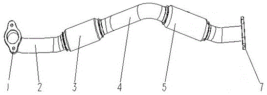
[0015] see figure 1 As shown, the inlet pipe assembly of the automobile muffler is welded by the inlet pipe 2, the first corrugated pipe 3, the connecting pipe 4, the second corrugated pipe 5, and the outlet pipe 6 in sequence. Wherein the length of the first bellows 3 is shorter than the length of the second bellows 5 . The inlet end of the inlet pipe 2 is provided with a first flange 1 for connecting with a three-way catalytic converter 10 . The outlet end of the outlet pipe 6 is provided with a second flange 7 for connecting with a muffler (not shown in the figure).

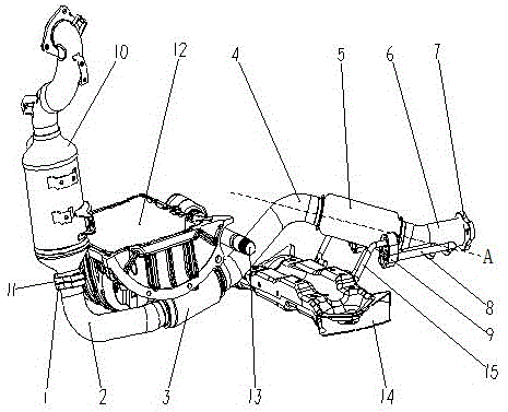
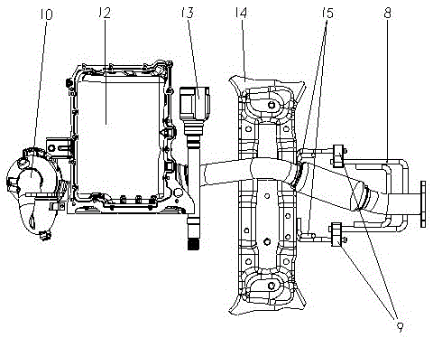
[0016] see figure 2 and image 3 As mentioned above, the arrangement structure of the muffler inlet pipe assembly includes the muffler inlet pipe assembly, the oil pan 12 , the transmission shaft 13 and the subframe 14 ...


PUM


Abstract

The invention discloses an automobile silencer inlet pipe assembly and an arrangement structure thereof. The automobile silencer inlet pipe assembly is formed by an inlet pipe, a first bellows, a connecting pipe, a second bellows and an outlet pipe which are connected in sequence. The inlet end of the inlet pipe is provided with a first flange used for being connected with a three-way catalytic converter, and the outlet end of the outlet pipe is provided with a second flange used for being connected with a silencer. The first bellows is arranged below an engine oil pan and a transmission shaft, and the second bellows is arranged above the rear of an auxiliary frame. According to the automobile silencer inlet pipe assembly, vibration generated by an engine and the silencer is effectively eliminated, reliability of a whole exhaust system is improved, and spatial safety distances of the exhaust system and parts such as the engine oil pan, the transmission shaft and the silencer and the heat damage requirements are met.

Description

technical field [0001] The present invention relates to automobile parts and its arrangement structure, more specifically to an automobile muffler inlet pipe assembly and its arrangement structure. Background technique [0002] Car engines can be divided into two types according to the arrangement of the intake and exhaust systems in the engine compartment: forward and rear type and front and rear type. For the front-rear engine, since the exhaust system with high temperature is located on the leeward side of the engine, it is relatively difficult to manage the heat in the cabin, while the layout of the exhaust system is relatively simple. For the front-rear engine, since the exhaust system is located on the windward side of the engine, the thermal management of the engine room is relatively easy, but it poses a great challenge to the layout of the exhaust system: on the one hand, the layout space is limited, and it is necessary to meet the needs of engine oil. The safety c...

Claims


Application Information

Patent Timeline
Patent Type & Authority Patents(China)
IPC IPC(8): F01N13/08
Inventor 陈向阳陈生超戴永蓥李兵黄永波尚亚梅
Owner CHONGQING CHANGAN AUTOMOBILE CO LTD
Why Eureka
Try Eureka