Gyroscope of single-shaft micro electro mechanical system

A micro-electromechanical system and gyroscope technology, which is applied to gyroscope/steering sensing equipment, gyroscope effect for speed measurement, instrument and other directions, can solve the problem of large measurement result error, achieve small result error, good anti-vibration performance, The effect of simple structure

Active Publication Date: 2013-11-27
SENODIA TECH (SHANGHAI) CO LTD
View PDF5 Cites 14 Cited by
  • Summary
  • Abstract
  • Description
  • Claims
  • Application Information

AI Technical Summary

Problems solved by technology

[0003] The purpose of the present invention is to solve the problem that existing gyroscopes are applied to products with a

Method used


Image

  • Gyroscope of single-shaft micro electro mechanical system
  • Gyroscope of single-shaft micro electro mechanical system
  • Gyroscope of single-shaft micro electro mechanical system

Examples


Embodiment Construction

[0021] Below in conjunction with accompanying drawing and specific embodiment the present invention is described in further detail:

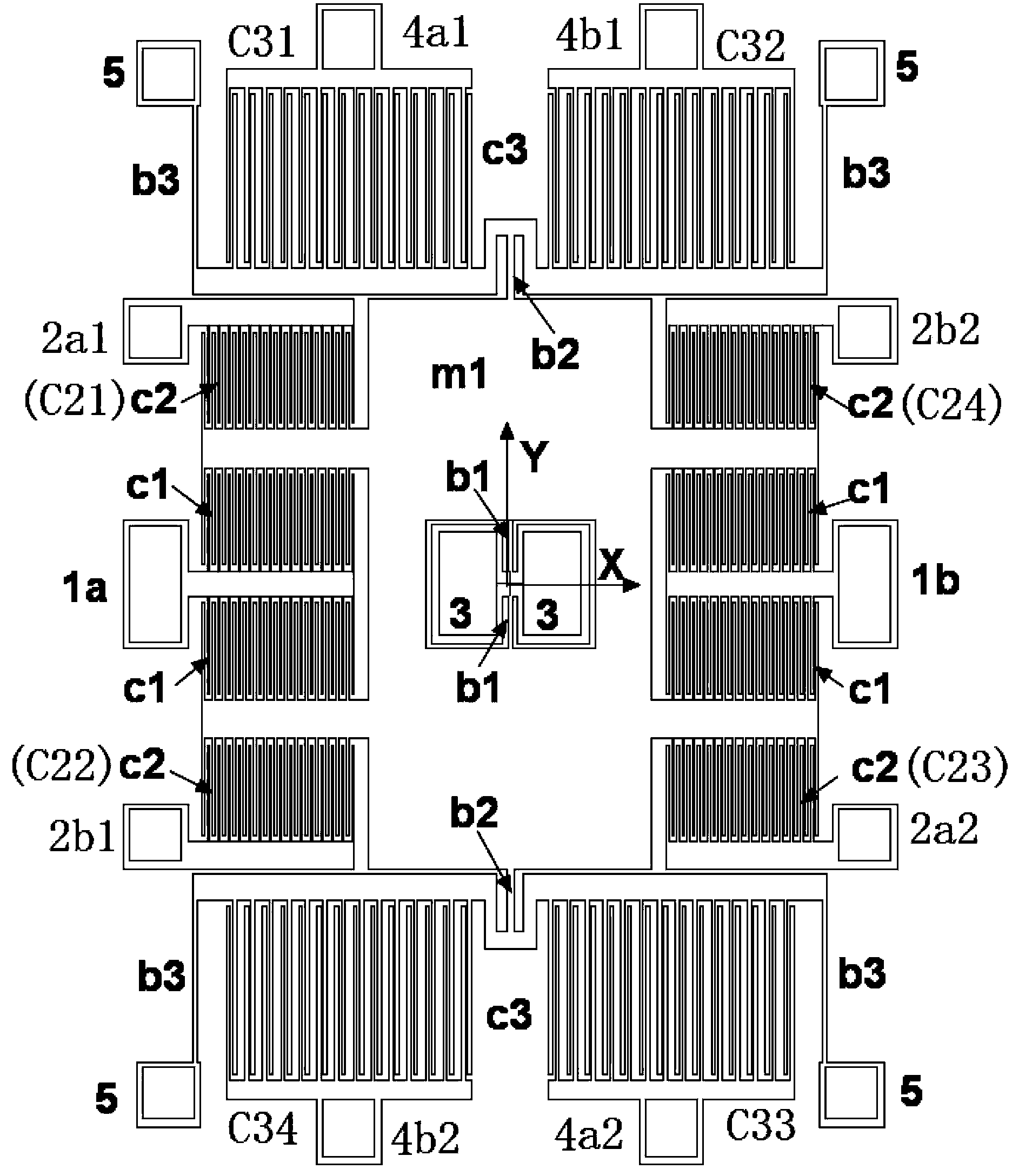
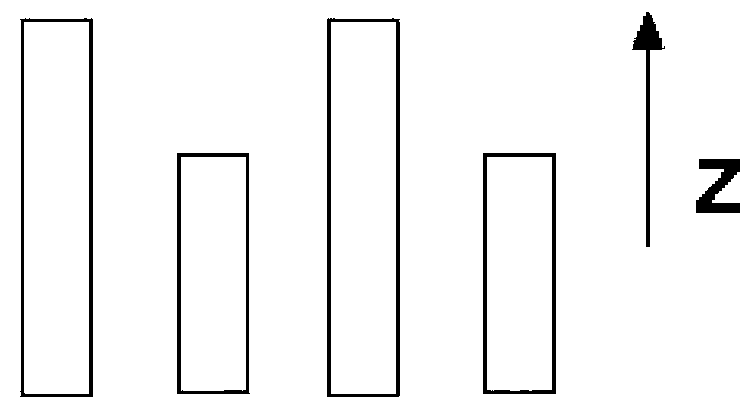
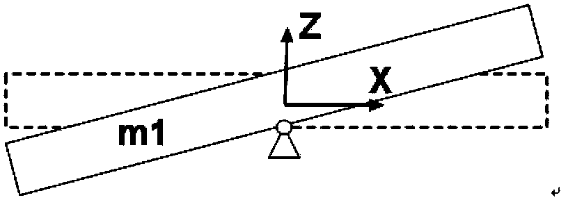
[0022] The specific structure of the single-axis MEMS gyroscope of the present invention will now be described by setting two pairs of driving capacitor groups C1, two pairs of detecting capacitor groups C2 and two pairs of sensitive capacitor groups C3 as an example. Define the x-axis direction of the Cartesian coordinate system with the center of the twisting mass m1 as the origin as the left and right directions, and the y-axis direction as the up and down directions, and the fixed and movable combs of each capacitor group have The height difference in the axial direction, such as figure 1 As shown, there are anchor points distributed around the twisting mass m1, and the area between the anchor point and the twisting mass m1 is the capacitor group setting area for setting various capacitor groups. The left, right, upper and lower capacitor g...


PUM


Abstract

The invention discloses a gyroscope of a single-shaft micro electro mechanical system. The gyroscope comprises a twist mass block, anchor points, and capacitor groups, wherein each capacitor group is arranged between a twist mass block and the corresponding anchor point; fixed comb teeth and movable comb teeth of the capacitor groups are fixed with a height difference along the z-axis direction; fixed comb teeth of driving capacitor groups are fixed on a base through the anchor points as driving electrodes; movable comb teeth of the driving capacitor groups are respectively connected with the twist mass block; fixed comb teeth of detection capacitor groups are fixed on the base through detection anchor points; movable comb teeth of the detection capacitor groups are connected with the twist mass block; a pair of detection electrodes composed of the detection anchor points are used for feeding back capacitance change signals to the pair of driving electrodes; fixed comb teeth of sensing capacitor groups are fixed on the base through sensing anchor points; movable comb teeth of the sensing capacitor groups are connected with the twist mass block through a periphery elastic beam; a central anchor point in the central part of the twist mass block is connected with the twist mass block through a middle elastic beam. The gyroscope disclosed by the invention has the characteristics that the structure is simple, and the error is smaller compared with that in angular velocity measurement result in the single movement.

Description

technical field [0001] The invention relates to a microelectromechanical system gyroscope, in particular to a single-axis microelectromechanical system gyroscope. Background technique [0002] MEMS (Micro Electro Mechanical System, Micro Electro Mechanical System) gyroscopes are small in size, low in cost, and good in integration, and have been used more and more widely, such as in mobile terminals, camera anti-shake, game handles, toy aircraft, navigation and other products middle. However, the structure of the MEMS gyroscopes currently on the market is relatively complex, and there are large errors in the measurement results, and the anti-vibration performance is relatively poor. Contents of the invention [0003] The purpose of the present invention is to solve the problem that the existing gyroscope is applied to a product with a single direction of motion, and the measurement result error is relatively large, and to provide a single-axis micro-electromechanical syste...

Claims


Application Information

Patent Timeline
IPC IPC(8): G01C19/5712
Inventor 邹波
Owner SENODIA TECH (SHANGHAI) CO LTD
Why Eureka
Try Eureka