
Inner rotor type gyro motor testing device

A technology of a gyro motor and a test device, which is applied to the measurement device, the test of mechanical parts, the test of machine/structural parts, etc., can solve the problems of low test accuracy, limited space, and large error in the non-perpendicularity between the motor shaft and the sensor, etc. To achieve the effect of simple test method, improve test accuracy, improve verticality and parallelism

Active Publication Date: 2013-11-27
BEIJING PULIMEN ELECTRO MECHANICAL HIGH TECHN CO
View PDF3 Cites 13 Cited by
  • Summary
  • Abstract
  • Description
  • Claims
  • Application Information

AI Technical Summary

Problems solved by technology

At present, the gyro motor vibration acceleration and bearing stiffness testing equipment or devices used at home and abroad are mainly for the outer rotor type gyro motor, while the inner rotor type gyro motor needs a special fixing device when testing because the stator is located outside the rotor, and because the rotor is exposed The size and space of some effective measurement parts are limited, only 1.5mm to 2mm. Therefore, the vibration acceleration and bearing stiffness of the inner rotor type gyro motor have not been directly measured, and can only be verified indirectly through the single-axis turntable rotation resistance test and centrifugal test.
And the commonly used motor installation method is to use dovetail slot or V-groove clamping, which brings about a large error in the non-perpendicularity between the motor shaft and the sensor, and low test accuracy

Method used


Image

  • Inner rotor type gyro motor testing device
  • Inner rotor type gyro motor testing device
  • Inner rotor type gyro motor testing device

Examples


Embodiment Construction

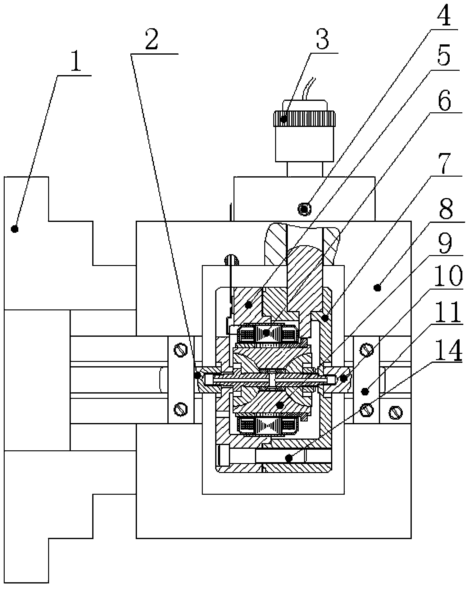
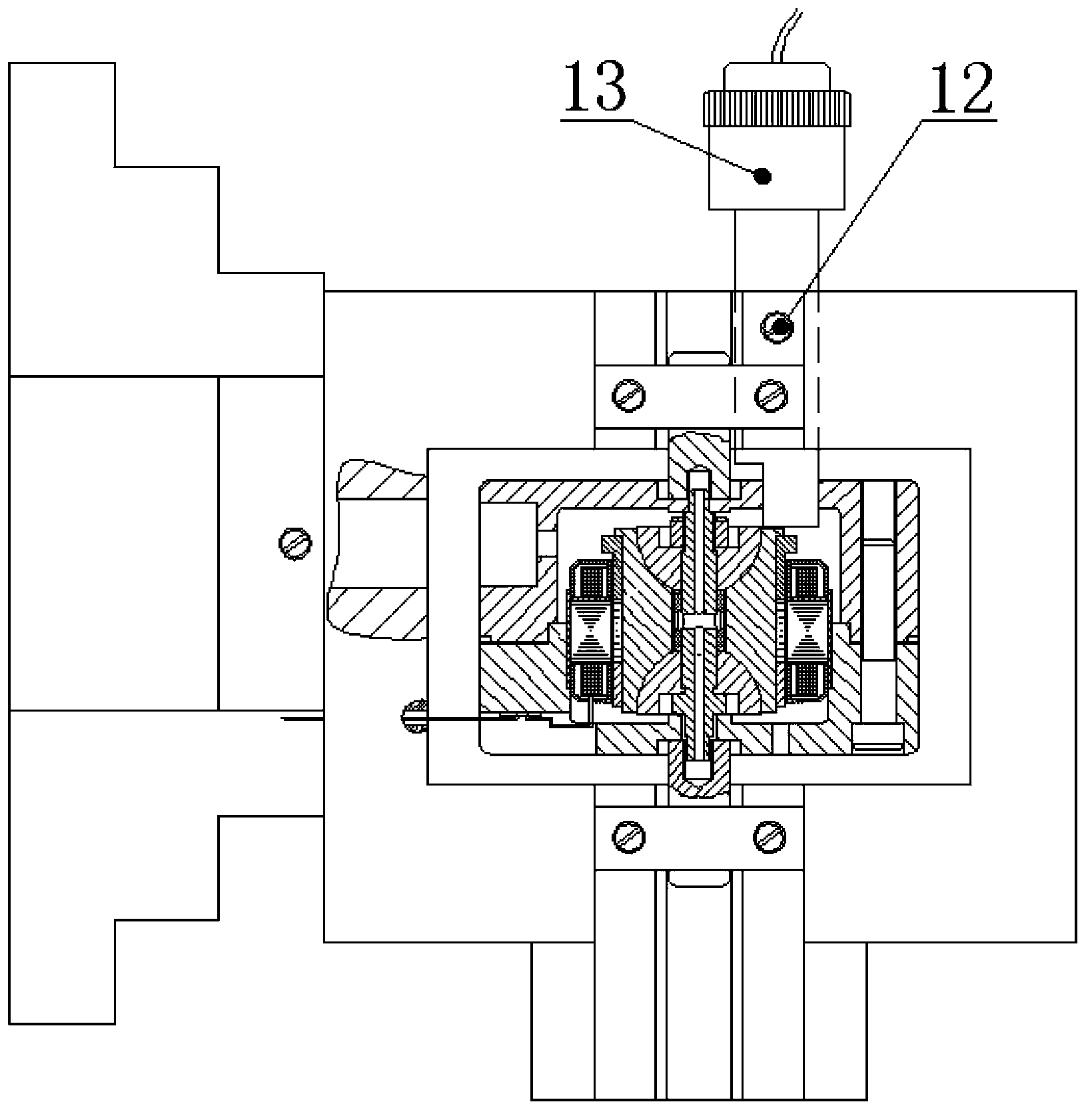
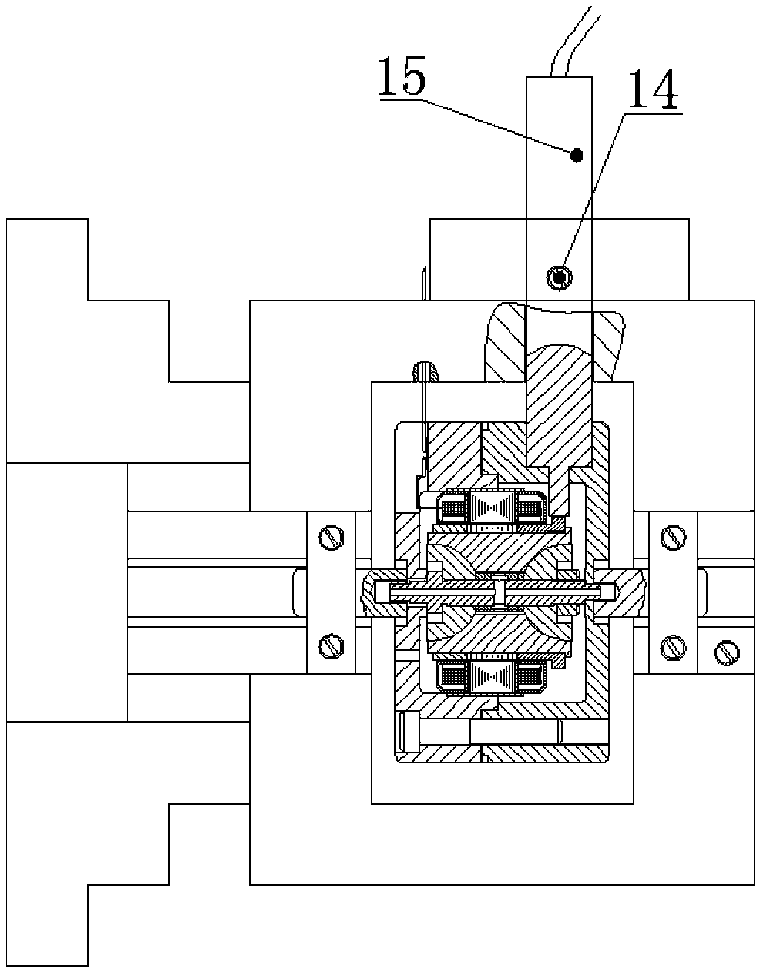
[0024] Such as figure 1 , figure 2 , image 3 As shown, the test device of the present invention includes a test bracket 8, an indexing head, a stator mounting seat, a first lock nut 2, a second lock nut 10 and two nut pressing blocks 11; the first lock nut 2 is threaded Connect the large shaft end of the gyro motor rotor 9, the second lock nut 10 is threadedly connected to the small shaft end of the gyro motor rotor 9, and the test bracket 8 and one of the nut pressing blocks 11 cooperate to form a socket for accommodating the first lock nut 2. Cylindrical cavity, the test bracket 8 and another nut pressing block 11 cooperate to form a cylindrical cavity for accommodating the second locking nut 10; The lock nut 10 is fixed on the test frame 8; the test frame 8 is clamped on the index head by the three claws 1 of the index head; the stator mounting seat is located in the test frame. Such as Figure 7 As shown, the stator mounting seat includes the upper stator mounting se...


PUM


Abstract

The invention discloses an inner rotor type gyro motor testing device. A locknut (2) and a locknut (10) are in threaded connection with the big shaft end and the small shaft end of a gyro motor rotor (9). A testing support (8) and nut lock blocks (11) are matched to form a cylindrical cavity used for accommodating the locknuts. The locknuts are fixed to the testing support (8) through the two nut lock blocks (11). A gyro motor stator (6) is installed inside an upper stator installation seat (5). The gyro motor rotor (9) is installed inside the gyro motor stator (6), and the end face of the big shaft end of the gyro motor rotor (9) is matched with the bottom surface of the upper stator installation seat (5) for positioning. The end face of the small shaft end of the gyro motor rotor (9) is matched with the bottom surface of a lower stator installation seat (7) for positioning. The lower stator installation seat (7) and the upper stator installation seat (5) are locked through a connecting bolt (14). The inner rotor type gyro motor testing device can test the vibration acceleration and the bearing stiffness, and a testing method is simple and accurate.

Description

technical field [0001] The invention relates to a test device for a gyro motor, in particular to a device for testing the vibration acceleration and bearing stiffness of an inner rotor type gyro motor. Background technique [0002] Gyro motor vibration acceleration and bearing stiffness are one of the key technical parameters for inertial instrument operation stability and accuracy. Gyro motors are divided into outer rotor type gyro motors and inner rotor type gyro motors according to their structure. At present, the gyro motor vibration acceleration and bearing stiffness testing equipment or devices used at home and abroad are mainly for the outer rotor type gyro motor, while the inner rotor type gyro motor needs a special fixing device when testing because the stator is located outside the rotor, and because the rotor is exposed The size and space of some effective measurement parts are limited, only 1.5mm to 2mm. Therefore, the vibration acceleration and bearing stiffness...

Claims


Application Information

Patent Timeline
IPC IPC(8): G01M13/00G01C25/00
Inventor 王晓瑜赵旺升崔砚曹清才小士王莎莎王锐苏义兵黄德袁媛
Owner BEIJING PULIMEN ELECTRO MECHANICAL HIGH TECHN CO
Learn More