Battery charging and discharging testing equipment and method

A charge-discharge test and battery technology, applied in the field of battery cycle charge-discharge test equipment, can solve the problems of high cost and complex structure, and achieve the effects of low cost, safe and reliable process, simple connection and structure

Inactive Publication Date: 2013-11-27
TIANJIN SANTROLL ELECTRIC AUTOMOBILE TECH CO LTD
View PDF6 Cites 21 Cited by
  • Summary
  • Abstract
  • Description
  • Claims
  • Application Information

AI Technical Summary

Problems solved by technology

[0002] The use of the battery is bound to be accompanied by the charging and discharging process again and again, and the battery will gradually age during the continuous charging and discharging process, so the anti-aging ability of the battery during charging and discharging is an important evaluation index to measure the performance of the battery. The traditional battery charge and discharge test equipment has complex structure and high cost, which is unaffordable for ordinary enterprises and users. Therefore, the charge and discharge test of batteries often needs to be completed by a special testing unit, but for many enterprises such as hybrid vehicles or pure electric vehicles Enterprises, the detection of vehicle batteries is a daily routine that needs to be carried out every day, so it is necessary to develop a battery charge and discharge test equipment and method with simple structure, low manufacturing cost and high reliability

Method used


Image

  • Battery charging and discharging testing equipment and method
  • Battery charging and discharging testing equipment and method

Examples


Embodiment Construction

[0027] The specific implementation manner of the present invention will be described below in conjunction with accompanying drawing, and the embodiment of the present invention will be described in further detail below in conjunction with accompanying drawing, and the following description about the embodiment of the present invention is only exemplary, not in order to limit the subject matter to be protected of the present invention For the embodiments described in the present invention, there are other changes within the protection scope of the claims, which all belong to the subject matter required to be protected in the present invention.

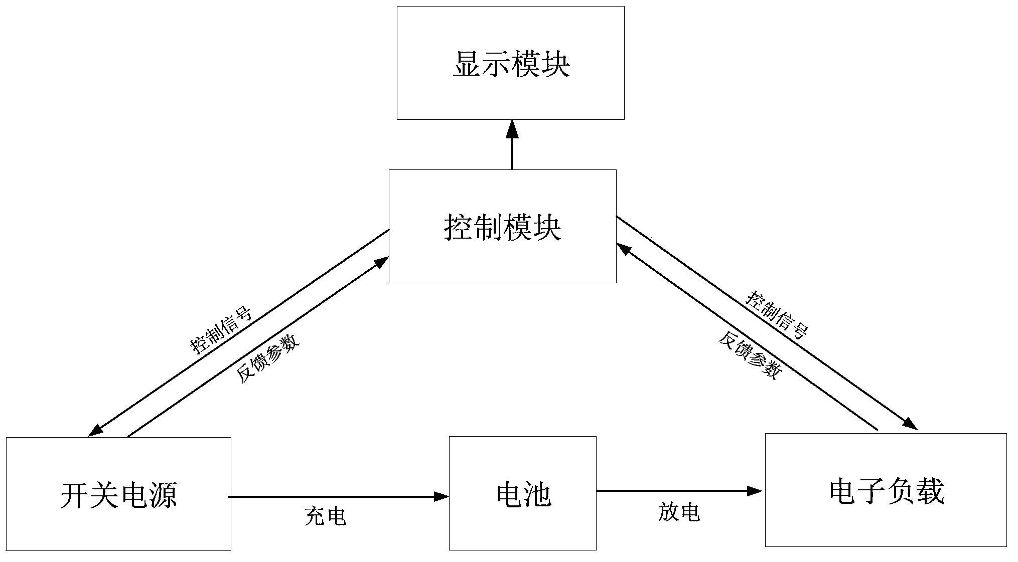
[0028] Such as figure 1 As shown, the charging device includes a control module, a switching power supply and an electronic load; the control module is respectively connected to the switching power supply and the electronic load; the control module transmits control signals to the switching power supply or the electronic load respectivel...


PUM


Abstract

The invention discloses a battery charging and discharging testing equipment and method. A control module is respectively connected with a switch power supply and an electronic load, and the switch power supply and the electronic load are respectively connected with the two electrodes of a battery to be tested; the switch power supply is turned off, the battery is charged with a constant current by the switch power supply, when a charging voltage is larger than or equal to U1, constant-voltage charging is carried out, and when the charging current is smaller than or equal to I2, the switch power supply is turned off, and stands for T hours; the electronic load is turned on, constant-current discharging is carried out, when the discharging voltage is smaller than or equal to U2, the electronic load is turned off, one testing time is added, the capacity of the battery is calculated, and if the capacity is larger than or equal to M, testing is continuously carried out, and if the capacity is smaller than or equal to M, testing is finished. The battery charging and discharging testing equipment and method aim to overcome defects in the prior art, the battery charging and discharging testing equipment which is composed of components such as the switch power supply, the electronic load and the control module is low in total cost and simple in system manufacturing and is operated through repeated circulating charging and discharging procedures, wherein the components such as the switch power supply, the electronic load and the control module are easy to operate.

Description

technical field [0001] The invention belongs to the field of battery performance testing, and in particular relates to a battery cycle charging and discharging testing device and method. Background technique: [0002] The use of the battery is bound to be accompanied by the charging and discharging process again and again, and the battery will gradually age during the continuous charging and discharging process, so the anti-aging ability of the battery during charging and discharging is an important evaluation index to measure the performance of the battery. The traditional battery charge and discharge test equipment has complex structure and high cost, which is unaffordable for ordinary enterprises and users. Therefore, the charge and discharge test of batteries often needs to be completed by a special testing unit, but for many enterprises such as hybrid vehicles or pure electric vehicles Enterprises, the detection of vehicle batteries is a daily routine that needs to be c...

Claims


Application Information

Patent Timeline
Patent Type & Authority Applications(China)
IPC IPC(8): G01R31/36
Inventor 董超曹新忠于新昌
Owner TIANJIN SANTROLL ELECTRIC AUTOMOBILE TECH CO LTD
Why Eureka
Try Eureka