Wide band low profile flat plate slot array antenna

A technology of slot array antenna and slot antenna, which is applied in the direction of slot antenna, antenna, antenna array, etc., can solve the problems of low efficiency, high profile, and narrow antenna frequency band, and achieve the effect of high efficiency, low profile, and increased isolation

Active Publication Date: 2013-11-27
BEIJING RES INST OF TELEMETRY +1
View PDF4 Cites 43 Cited by
  • Summary
  • Abstract
  • Description
  • Claims
  • Application Information

AI Technical Summary

Problems solved by technology

[0004] The technical problem of the present invention is: to overcome the deficiencies of the prior art, to provide a wide-band low-profile

Method used


Image

  • Wide band low profile flat plate slot array antenna
  • Wide band low profile flat plate slot array antenna
  • Wide band low profile flat plate slot array antenna

Examples


Embodiment Construction

[0026] The present invention will be further described in detail below in conjunction with the accompanying drawings and specific embodiments.

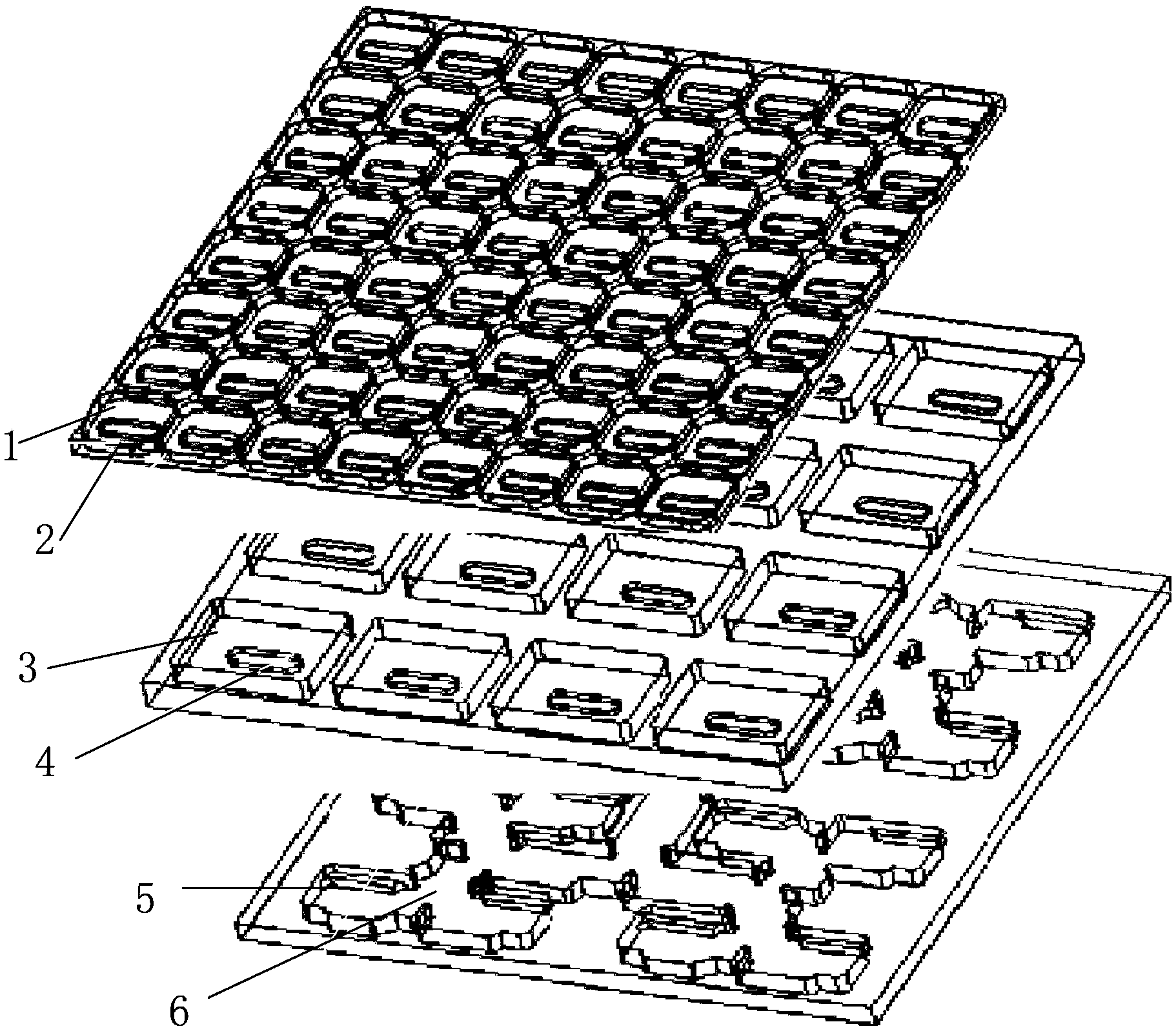
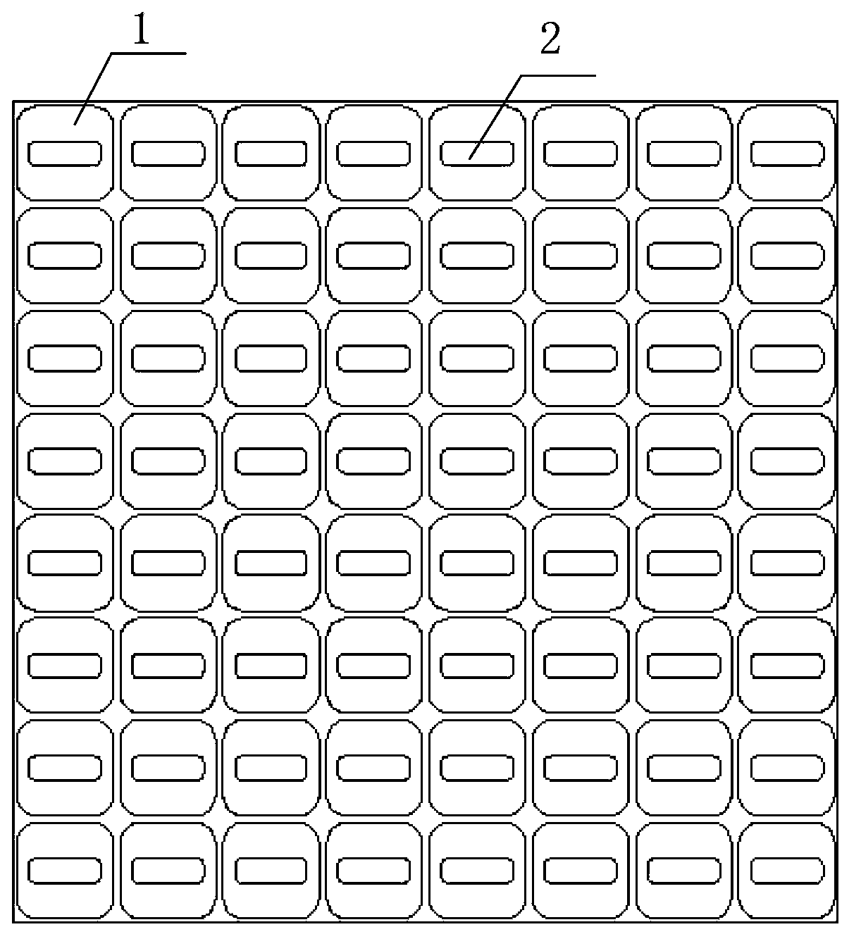
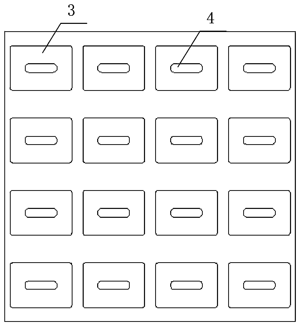
[0027] Such as figure 1 , 2 , 3, 4, 5, 6, and 7, a broadband low-profile panel slot array antenna of the present invention includes a broadband low-profile panel slot antenna unit 11 and a waveguide feeding network 6, wherein the broadband low-profile panel slot antenna The unit 11 also includes a radiation square cavity 1, a radiation slot 2, an excitation waveguide cavity 3, an excitation slot 4 and a feed waveguide 5. The total thickness of the array antenna of the present invention is about 0.6λ (λ is the free space wavelength).

[0028] Such as figure 2 , 6 , 7, the radiation square cavity 1 used to improve the radiation aperture efficiency and increase the isolation between adjacent radiation slots 2 is located directly above the radiation slots 2, and the distance between adjacent radiation slots 2 is the same as that of th...


PUM


Abstract

The invention discloses a wide band low profile flat plate slot array antenna which comprises wide band low profile flat plate slot antenna units and waveguide feed networks. Each wide band low profile flat plate slot antenna unit comprises a radiating square cavity, radiating slots, a stimulating waveguide cavity, a stimulating slot and a feed waveguide, wherein each waveguide feed network is composed of a plurality of equal-power-dividing and unequal-power-dividing waveguide H-T power dividers and connected with each power feeding waveguide, and the waveguide feed networks and the power feed waveguides are located in the same layer. Signals enter the feed waveguides through the waveguide feed networks and are transmitted to the stimulating waveguide cavities through the stimulating slots, the radiating slots enable the signals to be coupled out from the stimulating waveguide cavities, and then the signals are radiated to the free space through the radiating square cavities. The wide band low profile flat plate slot array antenna has the advantages of being wide in band, high in efficiency, low in profile and easy to machine, and is capable of being expanded to be a single pulse antenna after being combined with a comparator.

Description

technical field [0001] The invention relates to a wide-band low-profile flat-panel slot array antenna, which belongs to the technical field of flat-panel slot antennas. Background technique [0002] At present, the commonly used forms of panel antennas mainly include microstrip array antennas and waveguide slot array antennas. The microstrip array antenna has the advantages of low profile, light weight, and easy processing. However, when the frequency increases or the size of the antenna array becomes larger, the insertion loss of the microstrip antenna increases due to conductor loss and dielectric loss, and the efficiency is greatly reduced. high frequency and high gain applications. [0003] The waveguide slot array antenna is divided into waveguide slot traveling wave array and standing wave array. The waveguide slot antenna has the advantages of no dielectric loss, high efficiency and stable performance. The beams are inconsistent in the wide frequency range, which le...

Claims


Application Information

Patent Timeline
IPC IPC(8): H01Q21/00H01Q13/00H01Q13/18
Inventor 史永康孟明霞丁晓磊
Owner BEIJING RES INST OF TELEMETRY
Why Eureka
Try Eureka