A slow-wave device for strip-shaped electron injection double-slot trapezoidal line coupled cavity

A technology of strip electronics and coupled cavity, which is applied to the circuit components of transit-time electronic tubes, etc., can solve problems such as difficult heat dissipation, small size of coupled cavity traveling wave tube, and output power limitation.

Active Publication Date: 2021-05-14
UNIV OF ELECTRONICS SCI & TECH OF CHINA
View PDF5 Cites 0 Cited by
  • Summary
  • Abstract
  • Description
  • Claims
  • Application Information

AI Technical Summary

Problems solved by technology

But they each have their own advantages and disadvantages. The helical traveling wave tube has a very wide bandwidth, but the heat dissipation performance and output power are greatly limited; especially when the traveling wave tube works in the millimeter wave and submillimeter wave bands, due to the size of the helix Extremely small, difficult to dissipate heat, and its power capacity is smaller
Although the coupling cavity traveling wave tube has a much higher power output than the helix, due to the influence of the band edge oscillation, its bandwidth is narrow, and the coupling cavity traveling wave tube is small in size, requiring high processing and assembly precision

Method used


Image

  • A slow-wave device for strip-shaped electron injection double-slot trapezoidal line coupled cavity
  • A slow-wave device for strip-shaped electron injection double-slot trapezoidal line coupled cavity
  • A slow-wave device for strip-shaped electron injection double-slot trapezoidal line coupled cavity

Examples


Embodiment

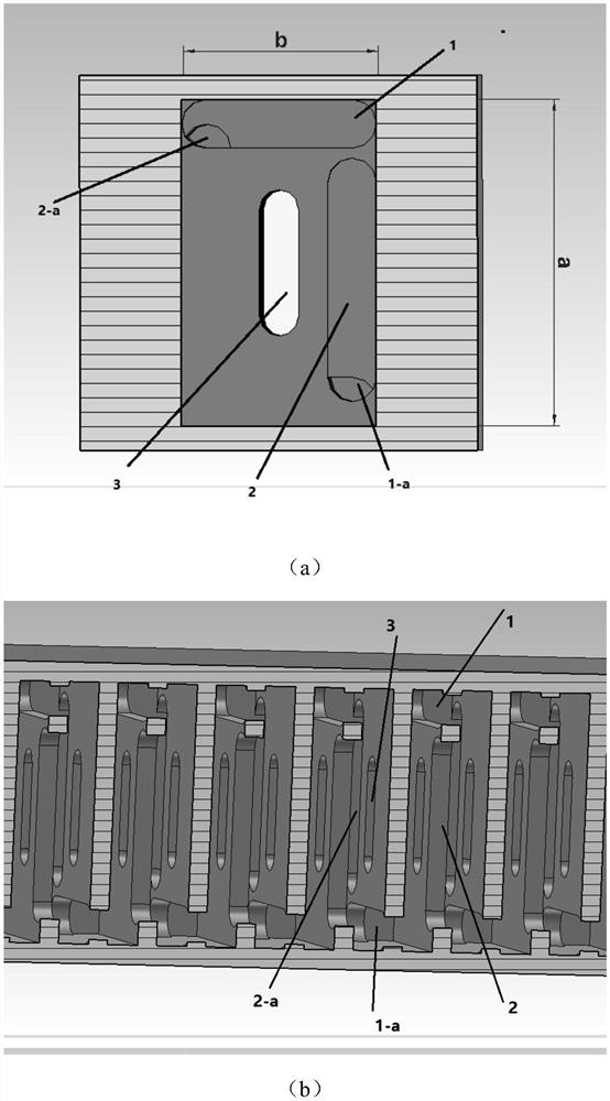
[0024] The present invention is a belt-shaped electronic injecting double-slot trapezoidal line-coupled cavity slow wave device, comprising: a plurality of cavities and cavity walls alternately connected with line-coupled cavities, and the front end and the end of the slow wave device are exactly the cavity wall;

[0025] Such as figure 1 As shown in (a), the coupling cavity is cut along the xoy plane, its cross-sectional shape is rectangular, and there are coupling grooves 1 and 2 with the same structure on the cavity wall;

[0026] The shapes of the coupling groove 1 and the coupling groove 2 are semicircular at both ends and a rectangle in the middle; wherein, the coupling groove 1 is close to the narrow side of the cavity and is parallel to the narrow side, and the coupling groove 2 is close to the wide side of the cavity and parallel to the wide side. The sides are parallel; in this embodiment, the shape of the coupling groove 1 and the coupling groove 2 can also be rect...


PUM


Abstract

The invention discloses a slow-wave device for belt-shaped electronic injecting double-slot trapezoidal line coupling cavity, which is composed of a plurality of cavities and line coupling cavities connected alternately with cavity walls, and each cavity wall is provided with a cavities close to each other A coupling slot with a narrow side and parallel to the narrow side, and a coupling slot that is close to the wide side of the cavity and parallel to the wide side, and a strip-shaped electron injector with a similar shape to the coupling slot parallel to the wide side is opened in the center of the cavity. channel; the electromagnetic wave transmitted along the cavity is coupled to the next cavity by the coupling slot. When the electron injection is injected into the strip-shaped electron injection channel, it interacts with the high-frequency field electromagnetic wave in the cavity to exchange energy. The high-frequency field electromagnetic wave Electron beams are modulated, and the modulated electron beams hand over energy, thereby amplifying electromagnetic waves.

Description

technical field [0001] The invention belongs to the technical field of microwave electric vacuum devices, and more specifically relates to a slow-wave device for strip-shaped electron injecting double-slot trapezoidal line coupling cavity. Background technique [0002] Vacuum electronic devices are systems that use charged particles (usually electrons) to interact with electromagnetic waves in a vacuum, and convert the DC energy of the electron beam into electromagnetic wave energy output. [0003] The most widely used slow wave systems in traveling wave tubes are the helix and coupled cavity. But they each have their own advantages and disadvantages. The helical traveling wave tube has a very wide bandwidth, but the heat dissipation performance and output power are greatly limited; especially when the traveling wave tube works in the millimeter wave and submillimeter wave bands, due to the size of the helix Extremely small, heat dissipation is difficult, and its power capa...

Claims


Application Information

Patent Timeline
Patent Type & Authority Patents(China)
IPC IPC(8): H01J23/24
CPCH01J23/24
Inventor 王战亮罗瑾璟宫玉彬段兆云巩华荣路志刚潘攀
Owner UNIV OF ELECTRONICS SCI & TECH OF CHINA
Why Eureka
Try Eureka