Broadband Power Splitter with High Power Division Ratio Based on Three-wire Coupling Structure

A technology of three-wire coupling and power division ratio, which is applied to waveguide devices, circuits, connection devices, etc., can solve the problem of low power division ratio of broadband power splitters, and achieve the effect of high bandwidth, high power division ratio and widening bandwidth

Active Publication Date: 2019-06-18
XIDIAN UNIV
View PDF3 Cites 0 Cited by
  • Summary
  • Abstract
  • Description
  • Claims
  • Application Information

AI Technical Summary

Problems solved by technology

[0005] The purpose of the present invention is to overcome the defects of the above-mentioned prior art, and propose a high power division ratio broadband power divider based on a three-wire coupling structure, which is used to solve the technical problem of low power division ratio of the existing broadband power divider

Method used


Image

  • Broadband Power Splitter with High Power Division Ratio Based on Three-wire Coupling Structure
  • Broadband Power Splitter with High Power Division Ratio Based on Three-wire Coupling Structure
  • Broadband Power Splitter with High Power Division Ratio Based on Three-wire Coupling Structure

Examples


Embodiment 1

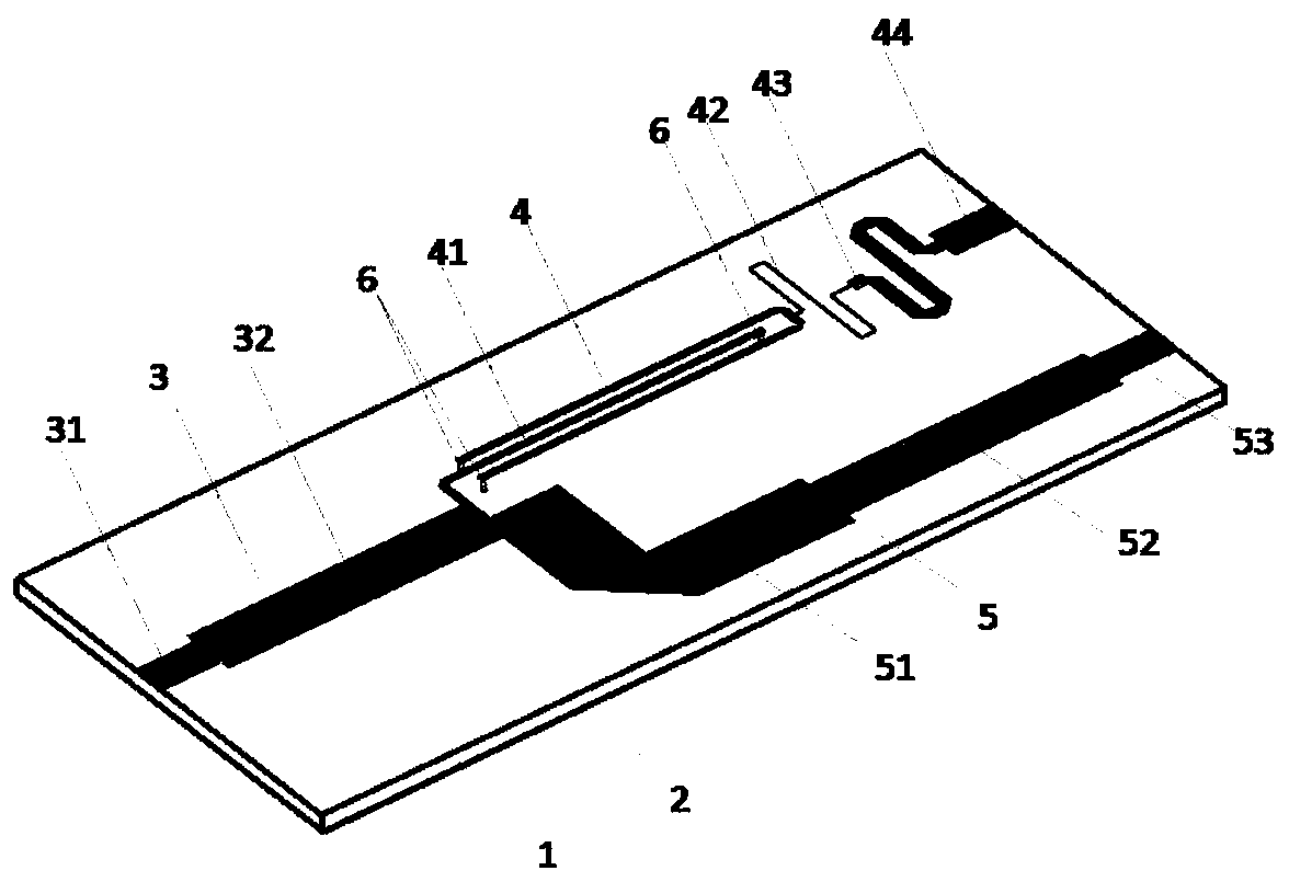
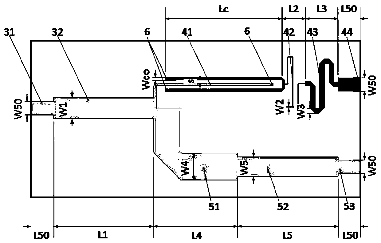
[0021] see figure 1 , this embodiment describes a broadband power divider with a center frequency of 2.4GHz and a power split ratio of 10:1, including a dielectric substrate 1 and a ground 2 on its lower surface, and a microstrip power divider printed on the upper surface of the dielectric substrate 1 The branch circuit includes a main branch 3 , a first branch 4 and a second branch 5 . Among them, the main branch 3 adopts a two-section stepped gradient microstrip structure, which is composed of interconnected microstrip transmission lines 31 and λ / 4 impedance converters 32, where λ is the wavelength of the electromagnetic wave in the dielectric substrate, which is used to realize the connection between the input port and the Impedance matching of the first stub and the second stub. The main branch 3 is connected with the first branch 4 and the second branch 5 through a T-shaped microstrip junction. The first branch 4 includes a parallel short-circuit three-wire coupling tra...

Embodiment 2

[0024] This embodiment describes a broadband power divider with a center frequency of 2.0 GHz and a power division ratio of 20:1. Except for the high impedance matching unit 42, its other structures are the same as those of Embodiment 1, and only some parameters are adjusted. The high impedance matching unit 42 is at power division ratio k 2 When >10, in order to achieve the high-impedance microstrip line required for impedance matching, the current processing technology cannot be realized, so a parallel short-circuited three-wire coupled transmission line is used, and the tail is provided with a metallized via hole, and the front end is connected to a parallel short-circuited three-wire coupled transmission line 41 , the rear end of which is connected to a serpentine microstrip line 43, and other structures are the same as those in Embodiment 1.

[0025]The preferred material of the dielectric substrate 1 is Rogers4003, and its dielectric constant ε r =3.55, the thickness of...


PUM


Abstract

The invention provides a high-power-dividing-ratio broadband power divider based on a three-wire coupling structure, and aims to solve the technical problem of low power dividing ratio of an existing broadband power divider. The broadband power divider comprises a dielectric substrate, a floor, a main branch knot, a first branch knot and a second branch knot, the floor is printed on the lower surface of the dielectric substrate, the upper surface of the dielectric substrate comprises a main branch knot, the first branch knot and the second branch knot, the main branch knot is of a two-step gradually-varied micro-strip structure, the first branch knot comprises a parallel short-circuit three-wire coupling transmission line, the tails of three transmission lines in the coupling transmission line are provided with metal through holes, the second branch knot is of a three-step gradually-varied micro-strip structure, and the first branch knot and the second branch knot are connected with the main branch knot through a T-shaped micro-strip knot. According to the broadband power divider, high-power-dividing-ratio characteristics are achieved on the premise of ensuring a broadband.

Description

technical field [0001] The invention belongs to the technical field of antennas, and relates to a high power split ratio unequal broadband power splitter, in particular to a high power split ratio broadband power splitter based on a three-wire coupling structure, which can be used as a feeder for antenna arrays in wireless communications in the electrical network. technical background [0002] Power divider, full name power divider, it can divide one input signal energy into two or more output signal energies that are equal or unequal, and is an essential component of radar and antenna array feed network. With the continuous development of broadband antenna technology and phased array antenna technology, higher requirements are placed on power splitters, with higher bandwidth requirements and larger power distribution ratios. It is to meet the demands of high bandwidth and high power ratio at the same time. At present, power splitters can be divided into two-way, three-way...

Claims


Application Information

Patent Timeline
Patent Type & Authority Patents(China)
IPC IPC(8): H01P5/12
CPCH01P5/12
Inventor 李文涛叶秀眺崔灿孙顺莱郭敏智史小卫
Owner XIDIAN UNIV
Why Eureka
Try Eureka