Distributed voltage-sharing control method for modular ISOS combined system
A combined system, equalizing control technology, applied in control/regulating systems, instruments, regulating electrical variables, etc., can solve the impact of lack of independence, system redundancy, reliability and scalability, ISOS combined system modularization problems such as low level, to achieve the effect of high system redundancy
- Summary
- Abstract
- Description
- Claims
- Application Information
AI Technical Summary
Problems solved by technology
Method used
Image
Examples
Embodiment 1
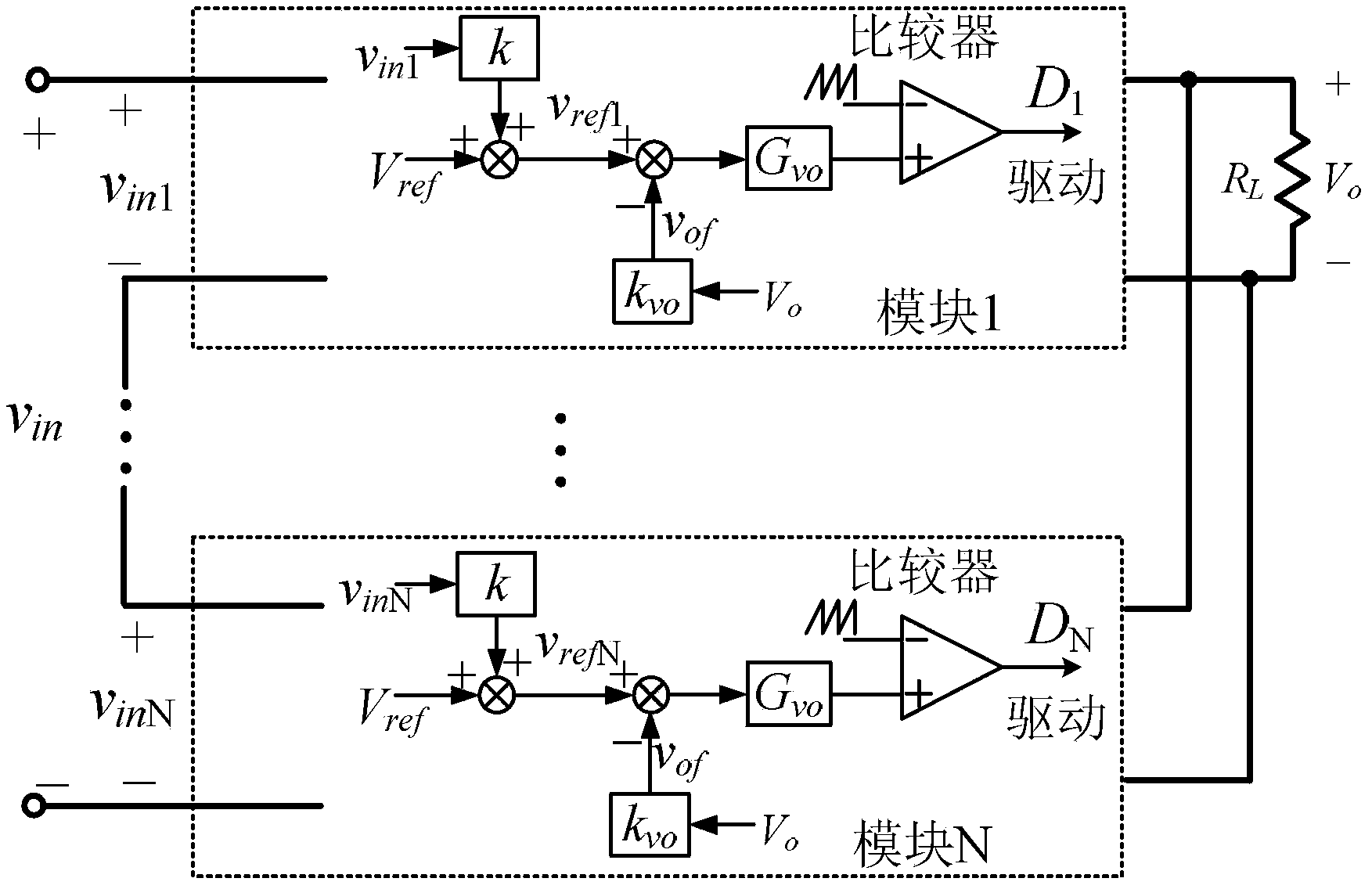
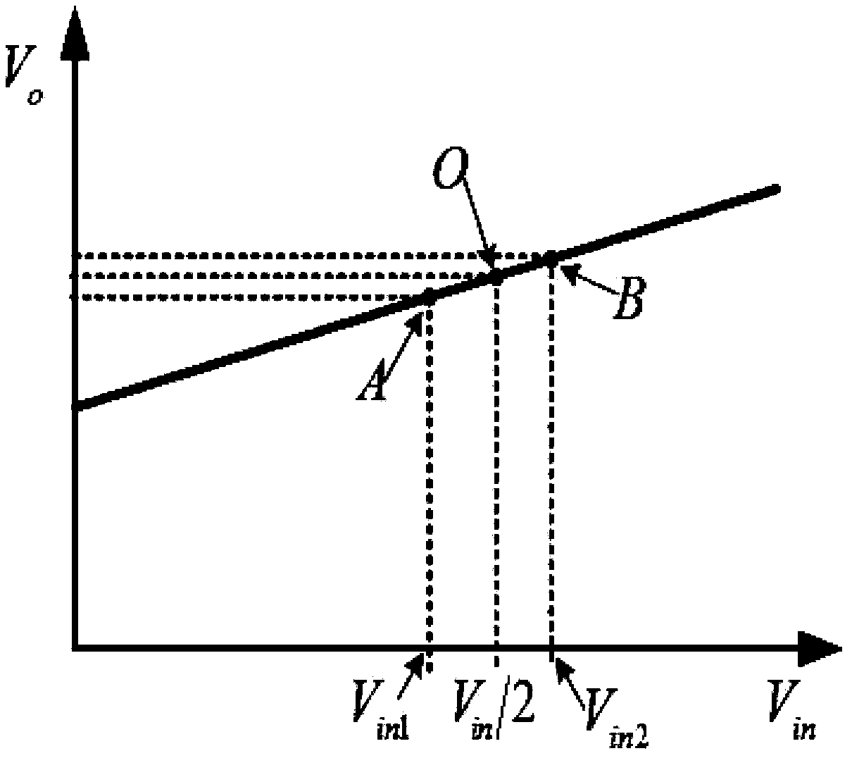
[0028] Embodiment 1: The input and output voltage equalization / current equalization control of the multi-converter ISOS system is very important. Each converter module has the same linear input and output characteristics, and it is a proportional linear relationship, which is the so-called upward warping characteristic. like figure 1 As shown, an ISOS system includes N converter modules, and each converter module has a control module. The control module samples the input voltage of the module and the output voltage of the system in real time, and performs corresponding calculation and control to realize voltage equalization control. The control module also includes a capacitor connected in parallel at the input end of the converter module.
[0029] The control method of the present invention will be explained in detail below. Assume that due to external disturbances, the module input voltage Vin1 of the first converter module decreases, while the module input voltage Vin2 of ...
Embodiment 2
[0037] Embodiment 2: as Figure 9 As shown, in this embodiment it is still assumed that due to external disturbances, the module input voltage Vin1 of the first converter module decreases, while the module input voltage Vin2 of the second converter module increases, and the system output voltage Vo remains unchanged. The difference between the first input sampling signal and the output sampling signal Vof is firstly obtained, and the obtained result is the difference signal Vof1 of the first module. The first module calculates the difference signal Vof1 and then calculates the difference with the reference signal Vref, and generates an adjustment signal according to the difference result. The adjustment signal is transformed by the output voltage adjustment function Gvo to adjust the duty of the PWM wave output to the converter. Ratio to reduce the input power, that is, Iin1 decreases, Icd1 increases, so that the voltage across the first capacitor Cd1 increases, that is, the m...
Embodiment 3
[0039] Embodiment 3: This embodiment adds an output voltage correction link on the basis of Embodiment 1, namely Figure 10 The dotted box part in each converter module. The first converter module first samples the module input voltage Vin1 of the first converter module according to the input sampling coefficient k to obtain a first input sampling signal. For the system output voltage Vo according to the output sampling coefficient k vo Sampling is performed and an output sampling signal Vof is obtained. Then subtract the reference signal Vref from the output sampling signal Vof and then perform sampling according to the sampling coefficient Kvc to obtain the first output voltage correction signal Vc1. Then the first input sampling signal is added to the reference signal Vref, and then compared with the first output voltage correction signal Vc1 to obtain the first module reference voltage Vref1, and finally the output sampling signal Vof is compared with the first module re...
PUM
 Abstract
Description
Claims
Application Information
 - R&D
- Intellectual Property
- Life Sciences
- Materials
- Tech Scout
- Unparalleled Data Quality
- Higher Quality Content
- 60% Fewer Hallucinations
Browse by: Latest US Patents, China's latest patents, Technical Efficacy Thesaurus, Application Domain, Technology Topic, Popular Technical Reports.
© 2025 PatSnap. All rights reserved.Legal|Privacy policy|Modern Slavery Act Transparency Statement|Sitemap|About US| Contact US: help@patsnap.com


