Vibration exciter based on piezoelectric stack

A technology of piezoelectric stack and exciter, which is applied in piezoelectric effect/electrostrictive or magnetostrictive motors, electrical components, generators/motors, etc. Problems such as less than 10KHz, acquisition signal distortion and noise, etc., achieve the effect of saving design space, less quantity, and small vibration displacement

Active Publication Date: 2013-11-27
NANJING UNIV OF AERONAUTICS & ASTRONAUTICS
View PDF3 Cites 19 Cited by
  • Summary
  • Abstract
  • Description
  • Claims
  • Application Information

AI Technical Summary

Problems solved by technology

[0004] The traditional vibrator driving device is a motor, which has a large vibration output force, but the output frequency band is narrow, which cannot meet the requirements of high frequency and small displacement excitation.
For example, when calibrating a piezoelectric sensor, it is necessary to generate an accurate high-frequency excitation signal, and the excitation frequency is required to reach 15KHz-20KHz, while the excitation frequency of the vibrator on the market generally cannot reach 10KHz; and if the output displacement is too large, The device to be excited will vibrate violently, resulting in distortion or excessive noise of the collected signal
Piezoelectric stack drivers can be used in precision machinery and instruments to achieve nanoscale displacement, force, and acceleration drives, and piezoelectric materials have a large operating frequency range. Common piezoelectric stacks are unpackaged and are usually used in applications. One end is pasted on the fixing part, the other end is pasted on the driving part, the assembly is inflexible, the piezoelectric stack is easy to be damaged during the disassembly process, and it is difficult to apply the pre-tightening force

Method used


Image

  • Vibration exciter based on piezoelectric stack
  • Vibration exciter based on piezoelectric stack
  • Vibration exciter based on piezoelectric stack

Examples


Embodiment Construction

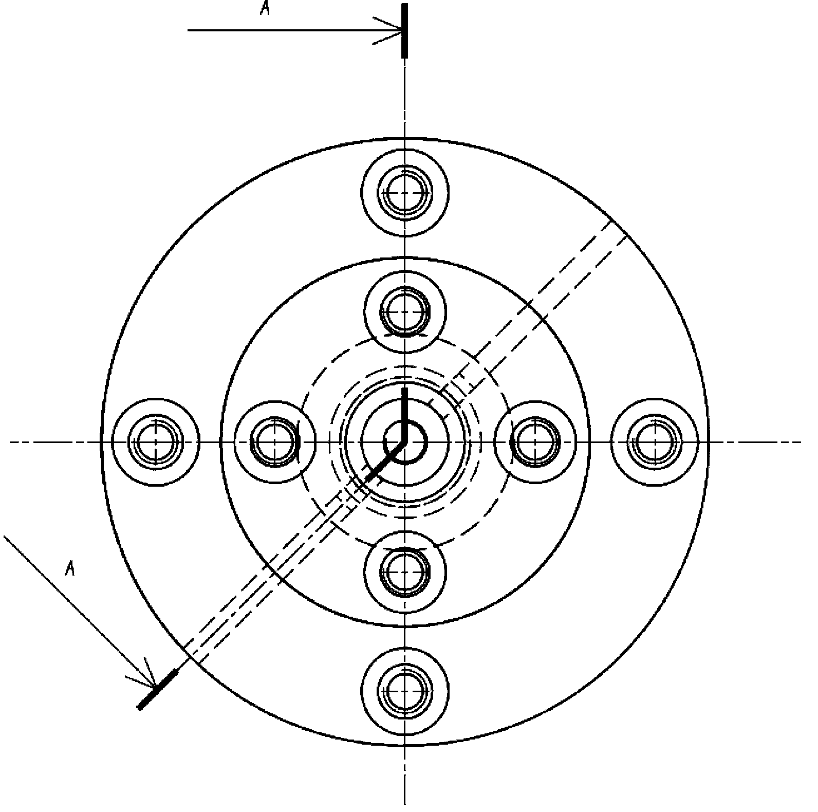
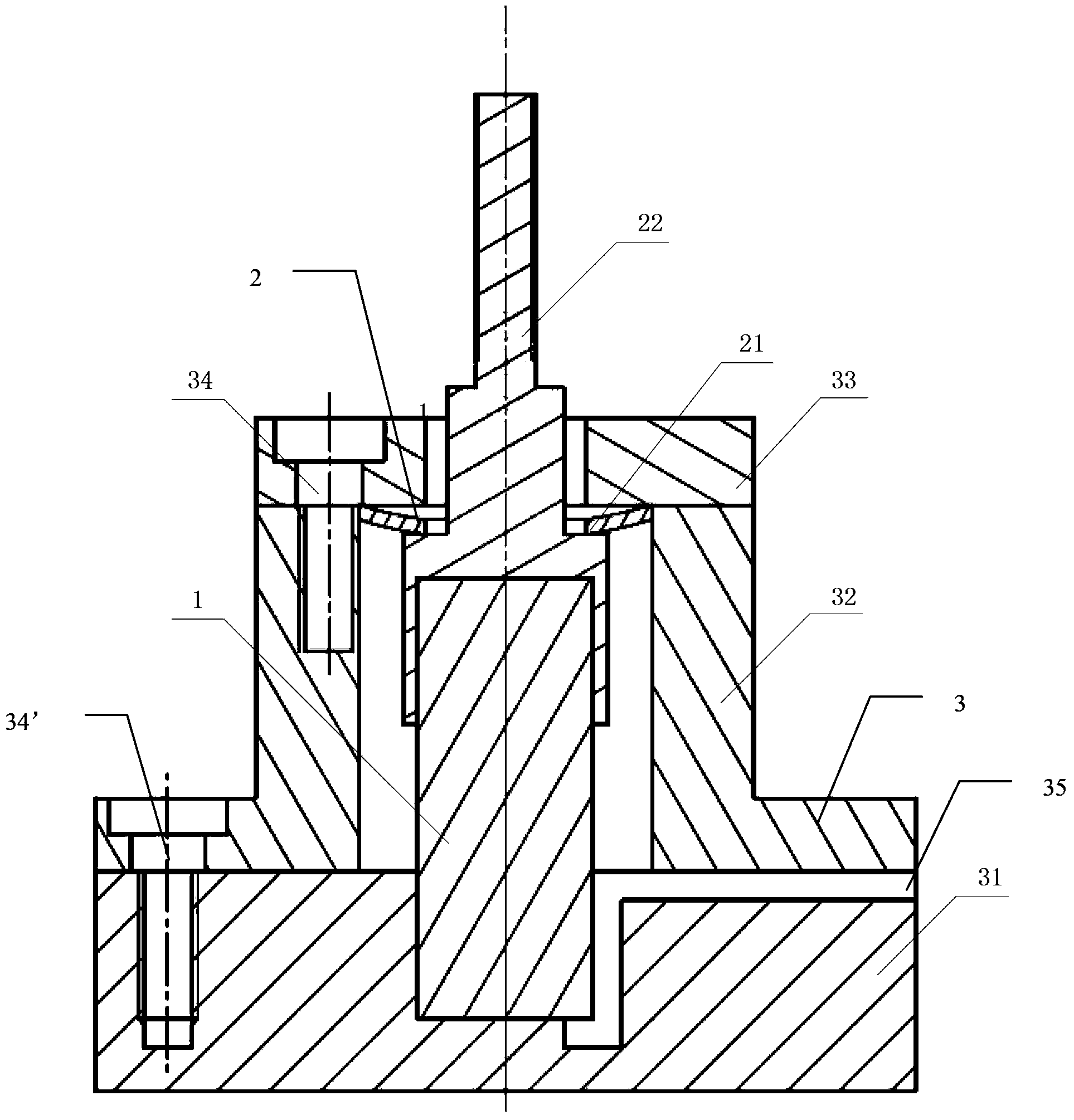
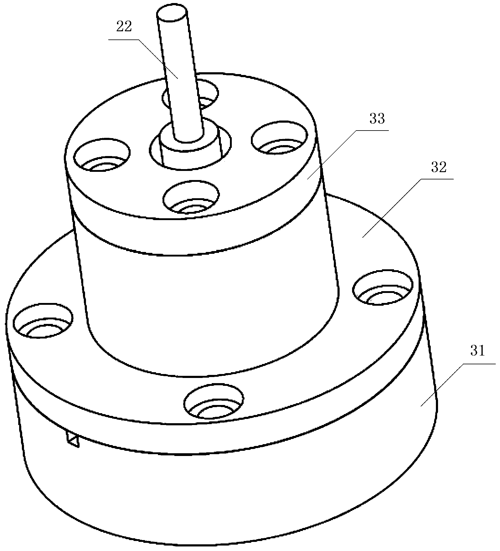
[0025] like figure 1 , figure 2 , image 3 As shown, the exciter based on the piezoelectric stack of this embodiment includes a piezoelectric stack driver 1, a vibration mechanism 2 and a packaging structure 3, and the piezoelectric stack driver 1 is fixedly arranged in the packaging structure 3, and the outside world The input signal is input to the piezoelectric stack driver 1 through the connecting wire passing through the packaging structure 3; the vibration mechanism 2 includes a butterfly spring 21 and a vibrating rod 22; the packaging structure 3 includes a base 31, a sleeve 32, The top cover 33, the top cover 33 and the sleeve 32 are connected by pre-tightening bolts 34, the base 31 and the sleeve 32 are connected by bolts 34'; one end of the piezoelectric stack driver 1 is fixed to the package On the base 31 of the structure 3, the other end is fastened to the end of the vibrating rod 22 facing the base 31; between.

[0026] like figure 2 As shown, one end of ...


PUM


Abstract

The invention discloses a vibration exciter based on piezoelectric stack. The vibration exciter comprises a piezoelectric stack driver, a vibrating mechanism and a packaging structure, wherein the piezoelectric stack driver is fixedly arranged in the packaging structure, and an outside input signal is input to the piezoelectric stack driver through a connecting wire penetrating through the packaging structure to drive the piezoelectric stack in the piezoelectric stack driver to vibrate. According to the technical scheme, the piezoelectric stack is adopted by the driver, the driving force of the piezoelectric stack is large, the output displacement of the piezoelectric stack is low, and the maximum output frequency of the piezoelectric stack is larger than 15 KHz. When loaded by sine alternating voltage, the piezoelectric stack can periodically vibrate along with the changes of the voltage, infinitesimal axial displacement is produced, and electric energy is converted into mechanical energy to be output. According to the vibration exciter, the components are simple, the number of the components is small, space needed by the design is saved, the structure is very compact, machining and assembling are easy, and the vibration exciter has the advantages of being high in output frequency, small in vibration displacement and size and easy to assemble. The vibration exciter is suitable for a high-precision driving, high-frequency-spectrum resonance driving and high-precision detecting system.

Description

[0001] technical field [0002] The invention relates to an exciter, in particular to an exciter based on piezoelectric materials, belonging to the technical field of precision machinery and instruments. [0003] Background technique [0004] The traditional vibrator driving device is a motor, which has a large vibration output force but a narrow output frequency band, which cannot meet the requirements of high frequency and small displacement excitation. For example, when calibrating a piezoelectric sensor, it is necessary to generate an accurate high-frequency excitation signal, and the excitation frequency is required to reach 15KHz-20KHz, while the excitation frequency of the vibrator on the market generally cannot reach 10KHz; and if the output displacement is too large, The device to be excited will vibrate violently, resulting in distortion or excessive noise of the collected signal. Piezoelectric stack drivers can be used in precision machinery and instruments to a...

Claims


Application Information

Patent Timeline
Patent Type & Authority Applications(China)
IPC IPC(8): H02N2/04
Inventor 季宏丽裘进浩邓文张超
Owner NANJING UNIV OF AERONAUTICS & ASTRONAUTICS
Why Eureka
Try Eureka