Survivable passive optical network planning method based on fiber-wireless integration

A passive optical network and optical network unit technology, which is applied in the field of indestructible passive optical network planning, and can solve the problems of ineffective implementation and high fiber deployment costs.

Active Publication Date: 2013-11-27
STATE GRID CORP OF CHINA +1
View PDF5 Cites 20 Cited by
  • Summary
  • Abstract
  • Description
  • Claims
  • Application Information

AI Technical Summary

Problems solved by technology

However, these methods usually require high fiber deployment costs, and due to geographica

Method used


Image

  • Survivable passive optical network planning method based on fiber-wireless integration
  • Survivable passive optical network planning method based on fiber-wireless integration
  • Survivable passive optical network planning method based on fiber-wireless integration

Examples


Embodiment 1

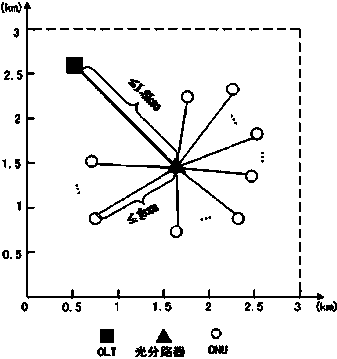
[0081] Such as image 3 As shown, a passive optical network is set up in a square area of ​​3km×3km, and the entire network area is divided into M×M grid units, where M∈{6,7,8,9,10}, each network The deployment cost of the wireless router on the cell center point is randomly generated between [1,4]. Randomly select the location of the OLT and the optical splitter, and the length of the main fiber between the two is less than 1.8km. N O ONUs are placed in the network according to uniform distribution, N O∈{8,10,12,14,16}, and the length of the branch fiber between each ONU and the optical splitter does not exceed 1km. All ONUs are allocated the same 20 units of capacity, and the business load of each ONU is in [5,d max ] Randomly generated between, d max ∈{8,10,12,14,16}. Configure a wireless function module for each optical network unit ONU as an interface device between the front-end wireless network and the back-end passive optical network. The transmission range of a...


PUM


Abstract

The invention belongs to the technical field of communication network, in particular relates to a survivable passive optical network planning method based on fiber-wireless integration. A wireless mesh network is formed by configuring a wireless function module for each optical network unit ONU and deploying a wireless router at the front end of the network, each working optical network unit ONU is allocated with one or more standby optical network units ONU; if one branch optical fiber fails, the working optical network unit ONU which is disconnected can transfer the service to its standby optical network unit ONU through a wireless standby route of the front end; the standby optical network unit ONU utilizes surplus capacity to bear the service from the working optical network unit ONU and uploads the service to an optical line terminal OLT; and the wireless router deployment cost is minimized under the condition of satisfying the hop count limit of the wireless standby route and fully protecting traffic. The survivable passive optical network planning method suffers small constraint from geographical environment, is conductive to reduce the service restoration time delay, and is suitable for large-scale survivable passive optical network planning.

Description

technical field [0001] The invention belongs to the technical field of communication networks, in particular to an indestructible passive optical network planning method based on optical fiber-wireless fusion. Background technique [0002] As the "interface" between user terminals and the backbone network, the access network is responsible for aggregating user services and uploading them to the backbone network, while transmitting services from the backbone network to user terminals. Traditional access network technologies, such as DSL, usually provide an asymmetric transmission bandwidth of 1.5Mb / s downlink and 128kb / s uplink, which cannot meet the high bandwidth requirements of multimedia services such as video-on-demand and online games. Although the emerging VDSL technology can support a downlink transmission bandwidth of 50Mb / s, its limited transmission distance is about 500m, which greatly limits the coverage of the access network. With the increasingly mature technol...

Claims


Application Information

Patent Timeline
IPC IPC(8): H04B10/032H04B1/74H04Q11/00
Inventor 李然许纯信孟凡博符太懿王忠波
Owner STATE GRID CORP OF CHINA
Why Eureka
Try Eureka